
Special purpose machine tool for circular mold drilling

A special machine tool, ring die technology, applied in boring/drilling, drilling/drilling equipment, metal processing machinery parts, etc., can solve the problem of increasing the difficulty of alignment between the rotary table and the main shaft, and increasing the alignment and rotation of the staff. The time required for the workbench and other issues can achieve the effects of lowering temperature, safe and convenient use, and scientific and reasonable structure.

Inactive Publication Date: 2019-11-26
浙江合奥机械科技有限公司
View PDF1 Cites 2 Cited by
  • Summary
  • Abstract
  • Description
  • Claims
  • Application Information

AI Technical Summary

Problems solved by technology

[0004] The present invention provides a special machine tool for ring die drilling, which can effectively solve the problem of lifting and lowering and positioning when the CNC rotary table is not aligned, which increases the difficulty of alignment between the rotary table and the main shaft. Added issue with the time it takes for workers to align the rotary table

Method used


Image

  • Special purpose machine tool for circular mold drilling
  • Special purpose machine tool for circular mold drilling
  • Special purpose machine tool for circular mold drilling

Examples


Embodiment Construction

[0024] The preferred embodiments of the present invention will be described below in conjunction with the accompanying drawings. It should be understood that the preferred embodiments described here are only used to illustrate and explain the present invention, and are not intended to limit the present invention.

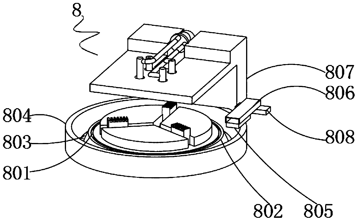
[0025] Example: such as Figure 1-4 As shown, the present invention provides a technical solution, a special machine tool for ring die drilling, including a machine bed body 1, a spindle seat 2 is installed on both sides of the top of the machine tool bed body 1, and the number of the spindle seat 2 is set to two , the number of main shafts 3 is set to four in total, and the four main shafts 3 can facilitate the drilling of the ring die, increase the punching speed of the ring die, and reduce the time required for punching the ring die. The tops of the two main shaft seats 2 Main shaft 3 is installed on both sides, hydraulic telescopic rod 4 is installed in the midd...


PUM


Abstract

The invention discloses a special purpose machine tool for circular mold drilling. The special machine tool comprises a machine tool bed body, wherein main shaft seats are arranged on the two sides ofthe top end of the machine tool bed body, and the two sides of the top ends of the two main shaft seats are correspondingly provided with main shafts; the middle part of the top end of the machine tool bed body is provided with a hydraulic telescopic rod, the middle part of the top end of the hydraulic telescopic rod is provided with a rotating table, and the middle part of the top end of the rotating table is provided with a clamping jaw; and a groove is formed in the middle end of the outer surface of the rotating table, and the middle part of the inner wall of the groove is provided with apositioning mechanism. The special purpose machine tool for the circular mold drilling is scientific and reasonable in structure, and safe and convenient to use; a bugle ring, a connecting ring, a connecting rod, a circular ring, a positioning rod, a limiting plate, a vertical plate, a fixing plate and the hydraulic telescopic rod are arranged, so that the lifting of the clamping jaw can be facilitated, and the lifting difficulty of the clamping jaw is lowered; and meanwhile, the clamping jaw can be positioned, the positioning difficulty between the clamping jaw and the main shafts is reduced, and the drilling machining of a circular mold on the clamping jaw can be further facilitated.

Description

technical field [0001] The invention relates to the technical field of special drilling machine tools, in particular to a special ring die drilling machine tool. Background technique [0002] The ring die is the key part of the pellet molding machine, and it is also the main wearing part of the pellet molding machine. The demand is relatively large. During the production process, it is easy to be blocked, especially when the new ring die (or new machine) is put into use, Its clogging rate is extremely high, and improper handling can easily cause damage, which not only affects production, but also makes the manufacture of the ring die more difficult and expensive. According to statistics, the loss cost of the ring die accounts for more than 25% of the maintenance cost of the entire production workshop At the same time, it has a direct impact on the quality of the extruded particles. The ring die drilling machine is a machine tool used to drill the ring die as the main process...

Claims


Application Information

Patent Timeline
Patent Type & Authority Applications(China)
IPC IPC(8): B23B41/00B23Q3/08B23Q11/10B23Q11/12
CPCB23B41/00B23Q3/062B23Q3/082B23Q11/1069B23Q11/127
Inventor 赵见平
Owner 浙江合奥机械科技有限公司
Learn More