Satellite beacon signal demodulation method, satellite beacon signal demodulation device, satellite beacon signal receiving method and satellite beacon signal receiving device

A satellite beacon and signal demodulation technology, which is applied in the field of high-precision satellite beacon signal demodulation, can solve the problems of small allowable frequency offset range, low sensitivity, rough frequency estimation, etc., and achieves improved dynamic range and high dynamic range. , the effect of small power jitter

Active Publication Date: 2019-11-22
四川安迪科技实业有限公司
View PDF6 Cites 2 Cited by
  • Summary
  • Abstract
  • Description
  • Claims
  • Application Information

AI Technical Summary

Problems solved by technology

[0003] Some conventional beacon demodulation methods are implemented by analog circuit design. Although digital signal processing has also been applied at present, the existing digital signal processing method is relatively simple, the frequency estimation is relatively rough, and there are low sensitivity and allowable frequency deviation. The scope is small and inflexible, and the application scene is relatively single. For example, in the document with the publication number CN208401847U, the filter design is single, the coefficient is fixed, and it is not suitable for more frequency offsets; in the document with the publication number CN108521292A, digital signal processing The module adopts an open-loop structure, and the estimation error of the signal frequency offset is large. The energy of the beacon signal will be damaged after sampling and filtering through the filter, resulting in a large error in the estimation of the beacon power.

Method used


Image

  • Satellite beacon signal demodulation method, satellite beacon signal demodulation device, satellite beacon signal receiving method and satellite beacon signal receiving device
  • Satellite beacon signal demodulation method, satellite beacon signal demodulation device, satellite beacon signal receiving method and satellite beacon signal receiving device
  • Satellite beacon signal demodulation method, satellite beacon signal demodulation device, satellite beacon signal receiving method and satellite beacon signal receiving device

Examples


Embodiment Construction

[0073] Embodiments of the present invention will be described in detail below in conjunction with the accompanying drawings.

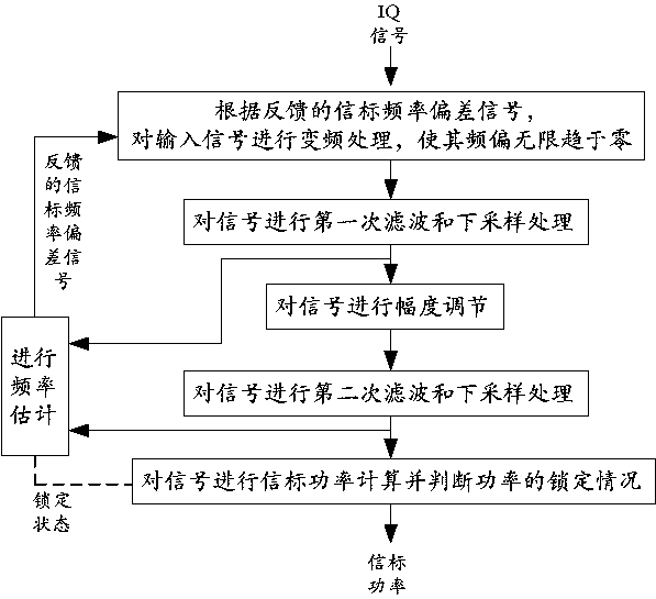
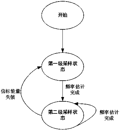
[0074] like figure 1 or figure 2 As shown, it is a flow chart of two methods in the embodiment of the method implementation mode of the present invention.

[0075] Specifically, a satellite beacon signal demodulation method adapted to a large frequency offset, comprising steps:

[0076] According to the feedback beacon frequency deviation signal, the input signal is frequency-converted so that its frequency deviation tends to zero infinitely;

[0077] Perform the first filtering and downsampling processing on the signal;

[0078] Adjust the amplitude of the signal;

[0079] Perform second filtering and downsampling processing on the signal;

[0080] Calculate the beacon power of the signal and judge the locking situation of the power;

[0081] In an initial state, the fed back beacon frequency deviation signal has a frequency deviation of 0.

...


PUM


Abstract

A satellite beacon signal demodulation method comprises the following steps: performing frequency conversion processing on an input signal according to a fed-back beacon frequency deviation signal, sothat the frequency deviation infinitely tends to zero; carrying out first filtering and down-sampling processing on the signal; carrying out amplitude adjustment on the signal; performing secondary filtering and down-sampling processing on the signal; carrying out beacon power calculation on the signals, and judging the locking state of the power. A satellite beacon signal demodulation device ischaracterized by comprising a frequency converter module, a first filter module, a digital automatic gain amplifier module, a second filter module and an energy estimation module which are connected in sequence, and further comprising a frequency estimation module. Beacon signal demodulation with a high dynamic range and high sensitivity is realized by adopting a digital closed-loop circuit feedback mechanism and a multi-stage digital filter structure, the method is suitable for relatively large beacon frequency deviation, and meanwhile, the demodulated and output beacon power is high in refreshing rate and high in stability, so that the method is suitable for relatively multiple types of satellite scenes, such as satellite communication in motion and satellite communication in static.

Description

technical field [0001] The invention relates to a single-carrier demodulation technology for satellite communication equipment, in particular to a high-precision satellite beacon signal demodulation method and device, and a receiving method and device that adapt to large frequency deviations. Background technique [0002] The beacon signal of the satellite is a single-carrier signal with a fixed frequency and amplitude transmitted by the satellite. It is a signal that characterizes the existence and related characteristics of the satellite. It is mainly used for antenna alignment and automatic tracking of satellite uplink earth stations. As we all know, the atmospheric environment in which the satellite is located is relatively complex, and the frequency and amplitude of the beacon signal it transmits will be shifted by the influence of the environment. Therefore, there is an urgent need for a beacon demodulation method with high sensitivity, high dynamic range and adaptabil...

Claims


Application Information

Patent Timeline
Patent Type & Authority Applications(China)
IPC IPC(8): H04L27/00H04L27/32
CPCH04L27/0014H04L27/32H04L2027/0026
Inventor 杜海英
Owner 四川安迪科技实业有限公司
Why Eureka
Try Eureka