
Method for aligning fingerprint sensing area of display element with fingerprint sensing module

A technology for display components and sensing areas, applied in the direction of acquiring/arranging fingerprints/palmprints, computer components, character and pattern recognition, etc., can solve problems such as poor fingerprint image quality, and achieve the effect of improving sensing performance

Pending Publication Date: 2019-11-22
EGIS TECH
View PDF5 Cites 1 Cited by
  • Summary
  • Abstract
  • Description
  • Claims
  • Application Information

AI Technical Summary

Problems solved by technology

[0004] The invention provides a method for aligning the fingerprint sensing area of ​​the display element with the fingerprint sensing module to solve the problem of poor quality of the sensed fingerprint image

Method used


Image

  • Method for aligning fingerprint sensing area of display element with fingerprint sensing module
  • Method for aligning fingerprint sensing area of display element with fingerprint sensing module
  • Method for aligning fingerprint sensing area of display element with fingerprint sensing module

Examples


Embodiment Construction

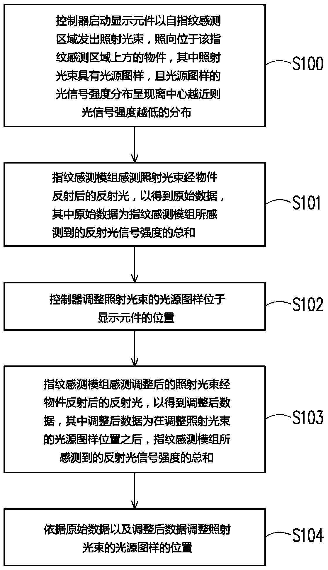
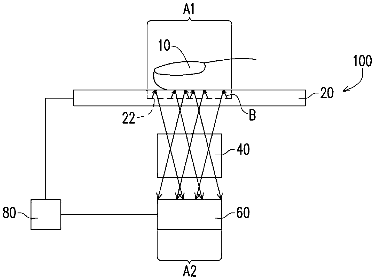
[0032] figure 1 It is a flow chart of the steps of the method for aligning the fingerprint sensing area of ​​the display element and the fingerprint sensing module according to an embodiment of the present invention. figure 2 It is a schematic diagram of an electronic device used in an embodiment of the present invention. Please also refer to figure 1 and figure 2 . An embodiment of the present invention provides a method for aligning the fingerprint sensing area 22 of the display element 20 with the fingerprint sensing module 60, which is at least applicable to figure 2 The electronic device 100 is shown, but the present invention is not limited thereto. The electronic device 100 is, for example, a portable electronic device such as a smart phone or a tablet computer. The electronic device 100 includes a display element 20, a light guide module 40, and a fingerprint sensing module 60, wherein the display element 20 has a fingerprint sensing area 22 for emitting an ill...


PUM


Abstract

A method for aligning a fingerprint sensing area of a display element with a fingerprint sensing module is suitable for an electronic device that includes a display element having a fingerprint sensing area, a controller, and a fingerprint sensing module. The alignment method includes: the controller activates the display element to emit an irradiating light beam from the fingerprint sensing areato an object which reflects the irradiating light beam to the fingerprint sensing module, wherein the light source pattern of the irradiating light beam exhibits a feature that the light signal intensity in a first area closer to the center is less than that in a second area far from the center; the fingerprint sensing module senses the reflected light formed by the irradiating light beam reflected by the object to obtain raw data, wherein the raw data is the sum of the reflected light signal intensity sensed by the fingerprint sensing module; the controller adjusts the position of the light source pattern at the display element; the fingerprint sensing module senses the adjusted reflected light to obtain the adjusted data, wherein the adjusted data is the sum of the reflected light signalintensity sensed by the fingerprint sensing module after the position of the light source pattern is adjusted; and the position of the light source pattern is adjusted based on the raw data and the adjusted data.

Description

technical field [0001] The present invention relates to a method for aligning a display element and a sensing module, and in particular to a method for aligning a fingerprint sensing area of ​​a display element and a fingerprint sensing module in an electronic device. Background technique [0002] With the continuous evolution and improvement of electronic technology and manufacturing technology, information electronic products are constantly being introduced. Computers, mobile phones, cameras and other electronic products are already necessary tools for modern people. In addition, today's smart mobile devices also need to integrate fingerprint recognition devices to enhance the security of the smart mobile devices and support more smart functions. [0003] Currently, users can press their fingers on the display or cover of the mobile phone for fingerprint recognition. However, during the sensing process, the brightness of the reflected light signal sensed by the sensing p...

Claims


Application Information

Patent Timeline
Patent Type & Authority Applications(China)
IPC IPC(8): G06K9/00
CPCG06V40/1318
Inventor 张榉馨曾俊钦
Owner EGIS TECH
Learn More