System and method for supplying heat to combined circulation machine group of last stage blades of cooling steam turbine

A technology of combined cycle unit and last-stage blades, which is applied in the direction of blade support elements, steam engine devices, combined combustion mitigation, etc., and can solve the problem of endangering the safe operation of the last-stage blades, the small amount of steam flowing through the final-stage blades, and the distributed energy capacity minor issues

Active Publication Date: 2019-11-22
ELECTRIC POWER RES INST OF GUANGXI POWER GRID CO LTD
View PDF7 Cites 7 Cited by
  • Summary
  • Abstract
  • Description
  • Claims
  • Application Information

AI Technical Summary

Problems solved by technology

However, due to the small capacity of distributed energy and the low capacity of its supporting turbogenerators, when steam is extracted for steam supply, the flow of steam through the final stage blades will be small, and the high temperature will be caused by the small flow of steam and insufficient cooling of the final stage blades. Endangering the safe operation of the last stage blade

Method used


Image

  • System and method for supplying heat to combined circulation machine group of last stage blades of cooling steam turbine
  • System and method for supplying heat to combined circulation machine group of last stage blades of cooling steam turbine
  • System and method for supplying heat to combined circulation machine group of last stage blades of cooling steam turbine

Examples


Embodiment Construction

[0032]In order to better understand the present invention, the present invention will be further described below in conjunction with accompanying drawing and specific embodiment:

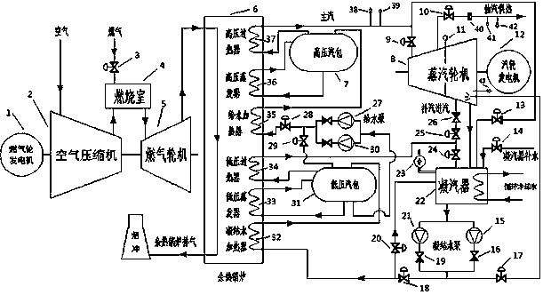
[0033] Such as figure 1 As shown, a combined cycle heat supply system for cooling the final stage blades of a steam turbine includes a gas turbine generator set, a waste heat boiler 6, a steam turbine generator set, a low-pressure steam drum 31, a high-pressure steam drum 7, a condensate pump, a feed water pump, and pipelines ,valve;

[0034] The gas turbine generator set includes a gas turbine generator 1, an air compressor 2, and a gas turbine 5; the gas turbine generator 1, the air compressor 2, and the gas turbine 5 are connected in sequence; the air compressor 2, and the gas turbine 5 are respectively connected to the combustion chamber 4; The chamber 4 is connected with the gas pipeline through the fuel regulating valve 3;

[0035] The waste heat boiler 6 includes a condensate heater 32, a l...


PUM


Abstract

The invention belongs to the technical field of combined circulation heat supply and control, and particularly relates to a system and a method for supplying heat to a combined circulation machine group of last stage blades of a cooling steam turbine. The system comprises a gas turbine generator group, an exhaust heat boiler, a steamer generator group, a low-pressure steam dome, a high-pressure steam dome, a condensation water pump, a water feeding pump, a pipeline and a valve, wherein steam supplementing is performed on the inner part of a steam turbine cylinder through a steam supplementingregulating valve mounted behind a rotating partition board, so that the last stage blades of the steam turbine are cooled caused by that the steam flow is increased, and the problems that the rotatingpartition board is closed to perform steam extraction for heat supply, and subsequent steam flow is reduced, so that the blasting of the last-stage blades is damaged by high temperature are solved; and when the power of a turbo generator is smaller than 30% of rated load, and the steam source for steam supplementing is insufficient, a steam exhaust cylinder water spray valve is automatically turned on to perform water spraying on a steam exhaust cylinder of the steam turbine, so that the temperature of the last stage blades of the steam turbine is reduced, and the problem that the last stageblades of the steam turbine are damaged is solved.

Description

technical field [0001] The invention belongs to the technical field of combined cycle heat supply and control, and in particular relates to a combined cycle heat supply system and method for cooling the last-stage blades of a steam turbine. Background technique [0002] Due to the small capacity of distributed energy, it is flexible to start and stop, and can quickly respond to power and heat demand, and plays an important role in maintaining the stability of the power grid. At the same time, due to its convenient layout, it can be installed near power users or heat users, reducing distance transmission The resulting network loss and heat loss is an effective way to heat power and heat for small boilers with low generation efficiency and serious air pollution. However, due to the small capacity of distributed energy and the low capacity of its supporting turbogenerators, when steam is extracted for steam supply, the flow of steam through the final stage blades will be small,...

Claims


Application Information

Patent Timeline
IPC IPC(8): F01D17/10F01D5/18F01D15/10F01K11/02F02C6/00F22D11/06
CPCF01D5/18F01D15/10F01D17/10F01K11/02F02C6/00F22D11/06Y02E20/16
Inventor 文立斌吴健旭卢广陵
Owner ELECTRIC POWER RES INST OF GUANGXI POWER GRID CO LTD
Why Eureka
Try Eureka