Distributed sewage treatment device with septic tank function

A sewage treatment device and a decentralized technology, applied in the directions of water/sewage multi-stage treatment, water/sludge/sewage treatment, sedimentation treatment, etc. Complex maintenance and other issues, to achieve the effect of reducing the content of suspended solids in the effluent, less sludge production, and simple operation and maintenance

Pending Publication Date: 2019-11-22
无锡博美环境科技有限公司
View PDF0 Cites 0 Cited by
  • Summary
  • Abstract
  • Description
  • Claims
  • Application Information

AI Technical Summary

Problems solved by technology

[0002] In recent years, with the rapid development of my country's economy, the pollution of water environment has become increasingly serious. For this reason, the country has invested a lot of money in the construction of centralized sewage treatment plants and supporting sewage collection pipe networks, and achieved certain results in maintaining and improving the water environment. However, For a large amount of rural domestic sewage, due to the problems of large investment scale, long construction period, and difficulties in the construction of supporting sewage collection pipe networks in the construction of centralized sewage treatment plants, decentralized treatment facilities are used to treat on-site discharge or reuse, without the need Investing a lot of money in pipeline network construction, less construction funds, short construction period, flexible site selection, is of great benefit to solving the problem of water pollution in our country
[0003] Existing household-type decentralized sewage treatment equipment usually adopts A / O (anoxic / aerobic) activated sludge method, biological contact oxidation method, SBR method and other processes or their variants. These technologies and equipment are generally not available For feces function, additional septic tanks need to be installed for pretreatment, and there are generally problems such as complicated process, scattered layout, large floor area, high energy consumption, and complicated operation and maintenance.

Method used


Image

  • Distributed sewage treatment device with septic tank function
  • Distributed sewage treatment device with septic tank function

Examples


specific Embodiment approach

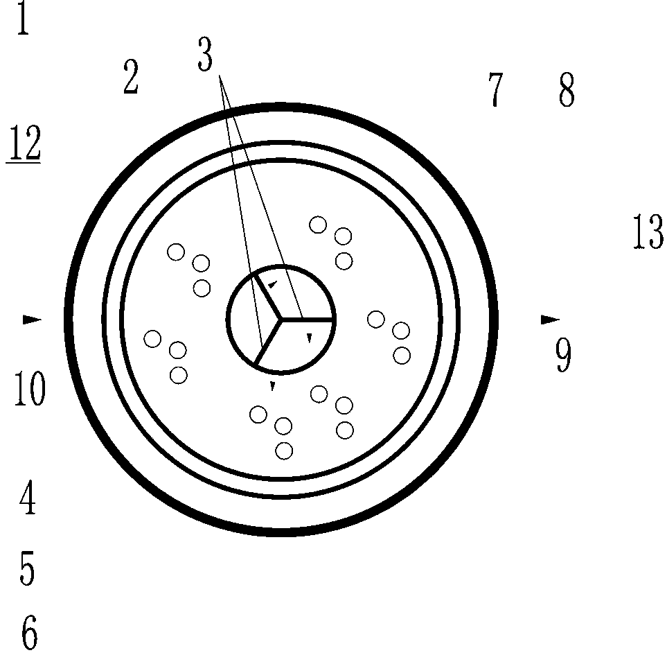
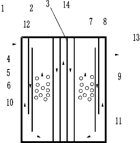
[0009] The specific embodiment: the present invention will be further described below in conjunction with the specific embodiment of accompanying drawing, figure 1 , figure 2 The structure shown is one of the preferred structures of the present invention. It is a decentralized sewage treatment device with septic function. It mainly includes a circular outer cylinder 1 and a central treatment tank 2. The central treatment tank 2 consists of a circular cylinder and a radial partition 3 arranged inside the circular cylinder, the partition 3 divides the central treatment tank into the first septic chamber 4, the second septic chamber 5 and the third septic chamber 6; the circular outer cylinder 1 and the central treatment tank 2 are provided with two concentric cylindrical partitions to divide the circular outer cylinder 1 and the central treatment tank 2 into a biochemical reaction zone 7, a diversion zone 8, and a clarification zone 9 from inside to outside; The first septic c...


PUM


Abstract

The invention aims to provide a distributed sewage treatment device with a septic tank function. The device comprises a circular outer cylinder and a central treatment tank, and the central treatmenttank is divided into a first septic chamber, a second septic chamber and a third septic chamber. Two concentric cylindrical partition plates are arranged between the circular outer cylinder and the central treatment tank to divide the space between the circular outer cylinder and the central treatment tank into a biochemical reaction area, a flow guide area and a clarification area from inside tooutside. The first septic chamber is connected with one water inlet, and the clarification area is connected with one water outlet. A biological suspended filler is placed in the biochemical reactionarea. An aeration device is arranged at the lower part in the biochemical reaction area and is connected with an air feeding pipe.

Description

technical field [0001] The invention belongs to the field of sewage treatment, in particular to a distributed sewage treatment device with septic function. Background technique [0002] In recent years, with the rapid development of my country's economy, the pollution of water environment has become increasingly serious. For this reason, the country has invested a lot of money in the construction of centralized sewage treatment plants and supporting sewage collection pipe networks, and achieved certain results in maintaining and improving the water environment. However, For a large amount of rural domestic sewage, due to the problems of large investment scale, long construction period, and difficulties in the construction of supporting sewage collection pipe networks in the construction of centralized sewage treatment plants, decentralized treatment facilities are used to treat on-site discharge or reuse, without the need Investing a lot of money in pipeline network constructi...

Claims


Application Information

Patent Timeline
Patent Type & Authority Applications(China)
IPC IPC(8): C02F9/14
CPCC02F3/30C02F2001/007
Inventor 张亮王冬梅韦龙孙振亮蒋燃刚
Owner 无锡博美环境科技有限公司
Why Eureka
Try Eureka