Injection mold structure suitable for forming power battery relay shell blank body

A power battery and injection mold technology, applied in the field of injection molds, can solve the problems of large product deformation, increased process, and large internal stress of the molding body, so as to improve product performance and yield, reduce air holes and cracks, and enhance sealing performance. Effect

Active Publication Date: 2019-11-22
LOUDI ANTAEUS ELECTRONICS CERAMICS
View PDF8 Cites 1 Cited by
  • Summary
  • Abstract
  • Description
  • Claims
  • Application Information

AI Technical Summary

Problems solved by technology

[0002] The existing power battery relay shell injection molding molds all adopt the method of feeding glue from the bottom of the product or from the small nozzle on the top surface of the product. The main disadvantages are: 1. The nozzle is connected to the embryo body, and the embryo body needs to be reprocessed to remove the nozzle. Increased process and bad
2. The internal stress of the molded body is large, the density is uneven, and the product is deformed after sintering
3. After the sintering of the product is completed, there are many pores inside the product, and the cracking phenomenon is serious, and the overall yield rate is only about 30%-40%

Method used


Image

  • Injection mold structure suitable for forming power battery relay shell blank body
  • Injection mold structure suitable for forming power battery relay shell blank body

Examples


Embodiment 1

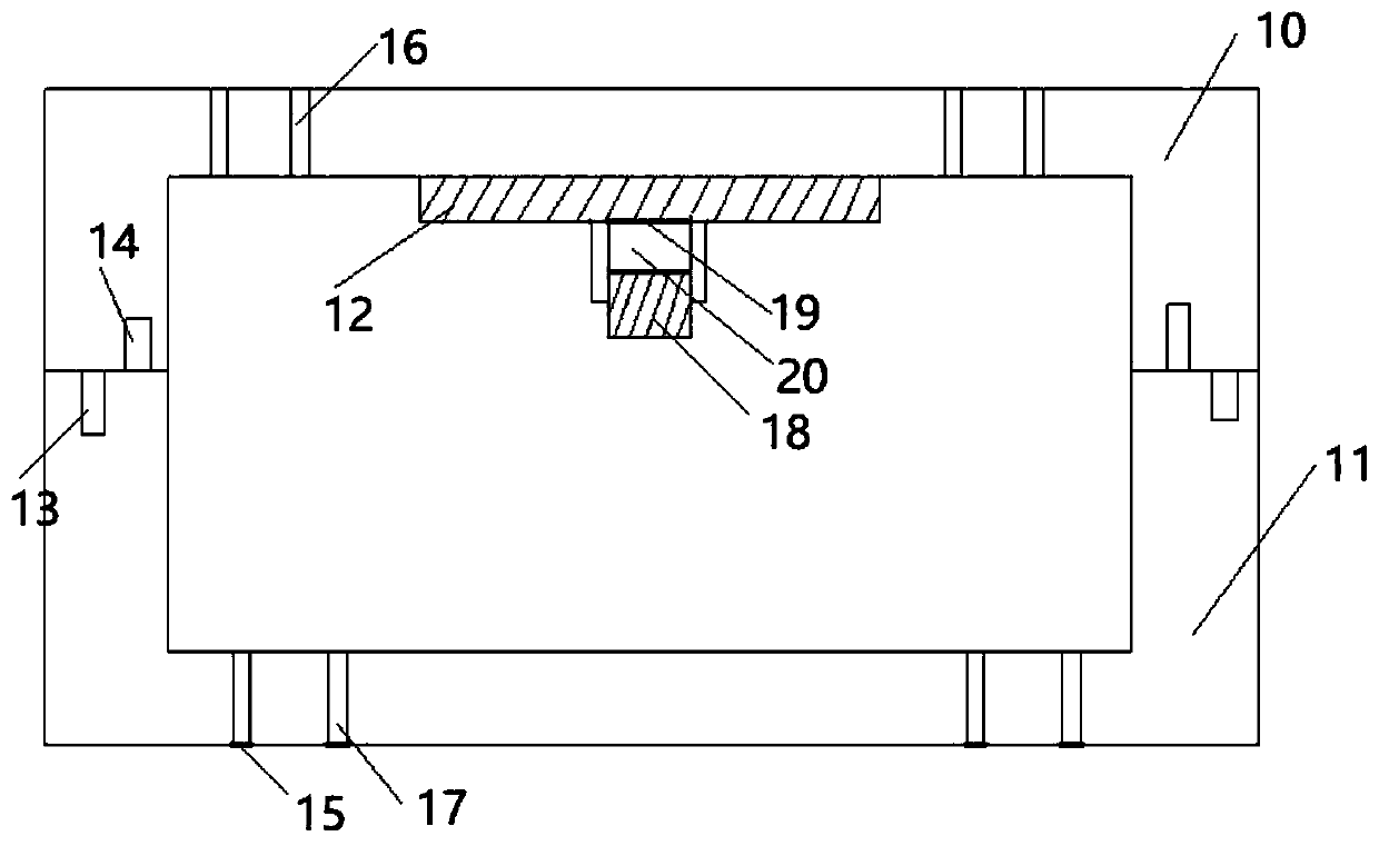
[0020] Such as figure 1 As shown, an injection mold structure suitable for forming a power battery relay shell blank body includes a hot runner nozzle 1, a nozzle 6, an injection molded part 2, an action cylinder 3, an injection machine ejector rod 9, and a cutting push plate 4, The nozzle needle push plate 7, the cutting needle 5, and the nozzle needle 8, the hot runner nozzle 1 and the nozzle 6 are fixed on the upper end of the injection molded part 2, and the nozzle needle 8 and the material cutting needle 5 are fixed below the injection molded part 2, The material cutting needle 5 is connected with the material cutting push plate 4, the nozzle needle 8 is connected with the water outlet needle push plate 7, the action cylinder 3 is fixed on the material cutting push plate 4, and the ejector rod 9 of the injection machine is fixed on On the nozzle needle push plate 7. The ceramic rubber enters the cavity of the injection molded part from the hot runner nozzle 1 to complete...


PUM


Abstract

The invention discloses an injection mold structure suitable for forming a power battery relay shell blank body. The injection mold structure comprises a hot runner nozzle, a gate, an injection moldedpart, an action cylinder, an injection molding machine ejector rod, a material cutting push plate, a gate needle push plate, a material cutting needle and a gate needle, wherein the hot runner nozzleand the gate are fixedly arranged on the upper end of the injection molded part; the gate needle and the material cutting needle are fixedly arranged below the injection molded part; the material cutting needle is connected with the material cutting push plate; the gate needle is connected with the gate needle push plate; the action cylinder is fixedly arranged on the material cutting push plate;and the injection molding machine ejector rod is fixedly arranged on the gate needle push plate. According to the injection mold structure, automatic demolding of the injection molding part from a semi-circular arc gate is realized, the product performance and the yield are greatly improved, the phenomena of air holes in a sintered finished product and cracking are reduced, and fluid overflowingin a cavity of the injection molded part is prevented during injection molding.

Description

technical field [0001] The invention relates to the technical field of injection moulds, in particular to an injection mold structure suitable for molding a power battery relay housing blank. Background technique [0002] The existing power battery relay shell injection molding molds all adopt the method of feeding glue from the bottom of the product or from the small nozzle on the top surface of the product. The main disadvantages are: 1. The nozzle is connected to the embryo body, and the embryo body needs to be reprocessed to remove the nozzle. Increased process and defects. 2. The internal stress of the molded blank is large, the density is uneven, and the product is deformed after sintering. 3. After the sintering of the product is completed, there are many pores inside the product, serious cracking, and the overall yield is only about 30%-40%. Contents of the invention [0003] The purpose of the present invention is to provide an injection mold structure suitable ...

Claims


Application Information

Patent Timeline
Patent Type & Authority Applications(China)
IPC IPC(8): B29C45/26B29C45/27B29C45/40B29C33/30
CPCB29C45/2606B29C45/2708B29C45/2725B29C45/4005Y02E60/10
Inventor 刘迪周伍康文涛张桓桓
Owner LOUDI ANTAEUS ELECTRONICS CERAMICS
Why Eureka
Try Eureka