
Filing and drilling machining bench work operation tool fixture

A technology for drilling machinery and fixtures, applied in the direction of manufacturing tools, metal processing, metal processing equipment, etc., can solve the problems of file sticking, waste of resources and idleness, affecting use, etc., and achieve the effect of improving work efficiency

Active Publication Date: 2019-11-22
青岛艾斯达特汽车科技有限公司
View PDF5 Cites 4 Cited by
  • Summary
  • Abstract
  • Description
  • Claims
  • Application Information

AI Technical Summary

Problems solved by technology

[0006] The present invention can solve the problem of existing fixtures for filing, drilling, machining and fitter work. Usually, the fixtures only limit the degree of freedom of the workpiece in one direction, and the workpiece is prone to deviation or shaking during the filing and drilling process, causing The surface of the workpiece is not smooth, the file is stuck, the drilling position is deviated, which affects the subsequent use, and even causes the workpiece to be scrapped. Usually, the tooling fixture can only hold the workpiece of a specific size, and different sizes of workpieces use different tools. Fixtures are easy to cause resource waste and idleness. After filing and drilling, the finished workpieces are usually picked up one by one manually. The work efficiency is low, the processing process is complicated, and it is easy to cause repetitive mechanical fatigue and other problems.

Method used


Image

  • Filing and drilling machining bench work operation tool fixture
  • Filing and drilling machining bench work operation tool fixture
  • Filing and drilling machining bench work operation tool fixture

Examples


Embodiment Construction

[0029] The embodiments of the present invention will be described in detail below with reference to the accompanying drawings, but the present invention can be implemented in many different ways as defined and covered by the claims.

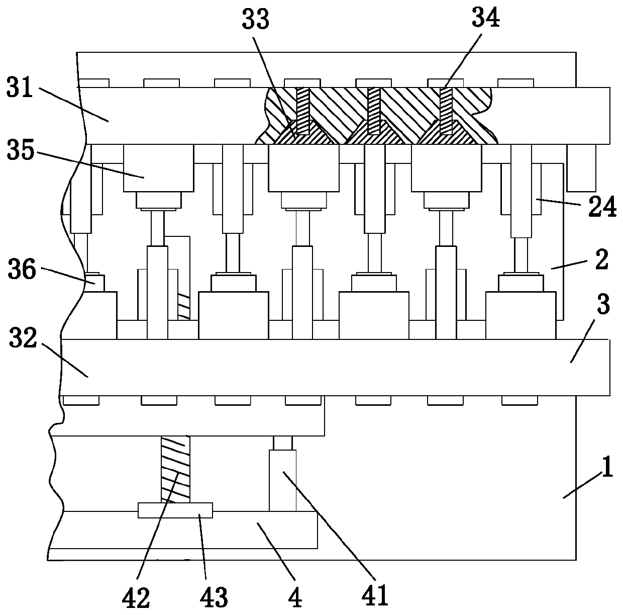
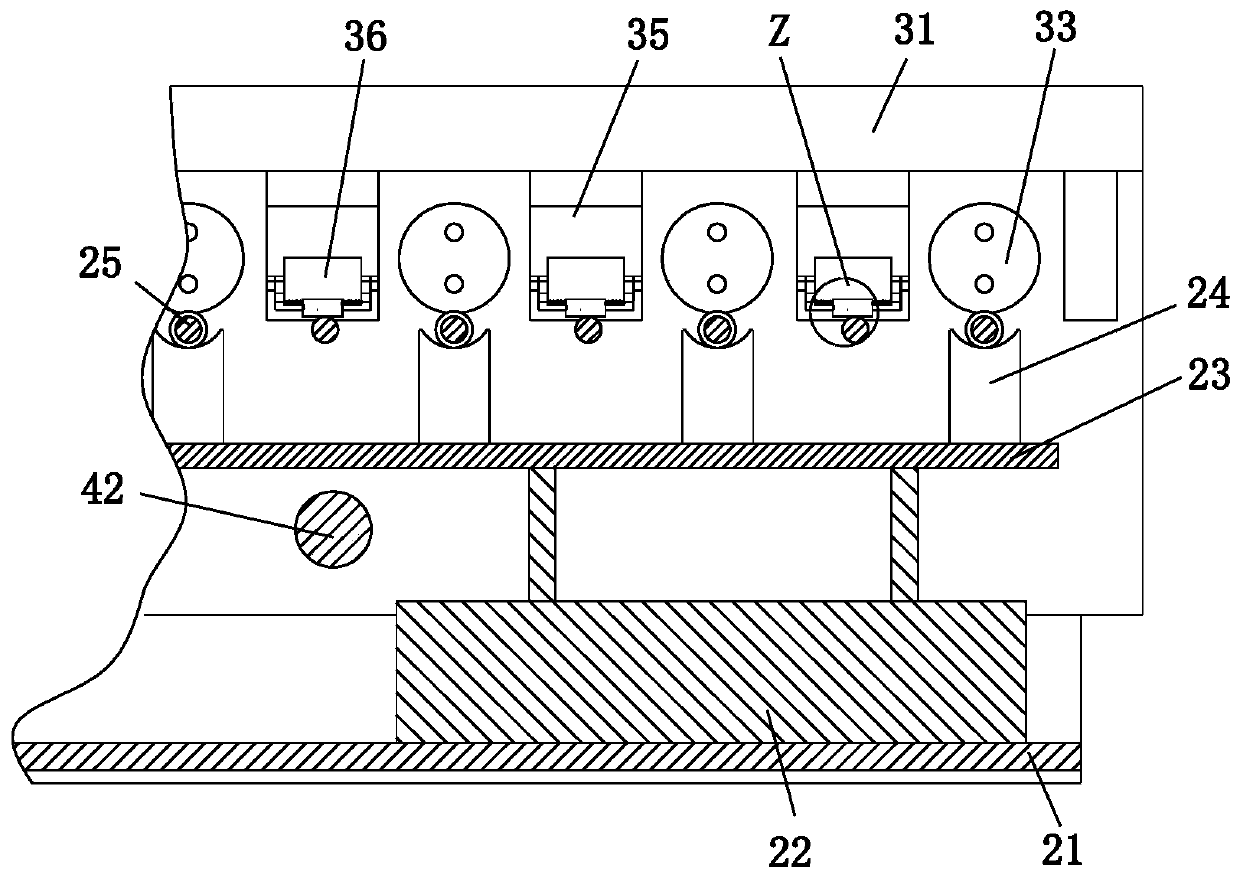
[0030] Such as Figure 1 to Figure 6 As shown, a kind of fixture for filing, drilling, machining and fitter work includes a workbench 1, a jacking device 2, a clamping device 3 and a transmission device 4. The middle part of the workbench 1 is provided with a rectangular through slot, and the inside of the rectangular through slot is A jacking device 2 is provided, a clamping device 3 is provided on the upper end of the workbench 1 , and a transmission device 4 is provided on the front side of the clamping device 3 .

[0031]The jacking device 2 includes a belt conveyor 21, a cylinder 22, a flat plate 23, a supporting block 24 and a telescopic rod 25, and the belt conveyor 21 is connected to the side wall of the rectangular channel through a slid...


PUM


Abstract

The invention relates to a filing and drilling machining bench work operation tool fixture which includes a worktable, a jacking device, a clamping device and a transmission device. A rectangular through slot is formed in the middle of the worktable, the jacking device is arranged in the rectangular through slot, the upper end of the worktable is provided with the clamping device, and the front side of the clamping device is provided with the transmission device. The filing and drilling machining bench work operation tool fixture can solve the problems that in an existing filing and drilling machining bench work operation tool fixture, only the degree of freedom of a workpiece in one direction is limited through the commonly adopted tool fixture, the workpiece is prone to deviating or shaking in the filing and drilling processes, consequently the filed surface of the workpiece is uneven, and a file is clamped; deviation of the drilling position happens, consequently subsequent use is influenced, and even rejection of the workpiece is caused; and the commonly adopted tool fixture can only clamp the workpiece in the specific size, different tool fixtures are used for the workpieces in different sizes, and consequently waste of resources and idleness are easily caused.

Description

technical field [0001] The invention relates to the field of mechanical tooling fixtures, in particular to a tooling fixture for filing, drilling, and machining fitters. Background technique [0002] Tooling, that is, process equipment: refers to the general term for various tools used in the manufacturing process, including props, fixtures, molds, inspection tools, etc. Fixtures are used to fix or install processing objects in the process of mechanical manufacturing so that they occupy the correct position , to accept construction or testing devices, also known as fixtures, fixtures have the characteristics of great versatility, high degree of standardization, fast operation, and safety. Fitter is a kind of metal processing technology including filing, drilling, tapping, etc. In general, it has the advantages of flexible processing, processing complex shapes and high-precision parts, and small investment. Nowadays, when filing and drilling workpieces, fixtures are usually u...

Claims


Application Information

Patent Timeline
Patent Type & Authority Applications(China)
IPC IPC(8): B23Q3/06B23Q1/25B23Q7/00
CPCB23Q1/25B23Q3/06B23Q7/00
Inventor 张秋龙陶娟王飞翔
Owner 青岛艾斯达特汽车科技有限公司
Learn More