Rolling high speed blender

A technology of wall breaker and crusher, applied in grain processing and other directions, can solve the problems of low processing efficiency, insufficient food processing, and small effective area, and achieve the effect of improving processing efficiency, fine food taste, and high processing efficiency.

Pending Publication Date: 2019-11-22
HENAN BROTHER TECH DEV CO LTD
View PDF0 Cites 0 Cited by
  • Summary
  • Abstract
  • Description
  • Claims
  • Application Information

AI Technical Summary

Problems solved by technology

[0004] This method of destroying the cell wall by cutting or impacting the blade, because the action areas of the blade and the impact are lines and points respectively, the force is sufficient, but the effective area is too small and the food treatment is not sufficient, resulting in low processing efficiency and broken pieces. The problem that the food is not delicate enough, due to the flaws in the principle, no matter how the speed is increased, it cannot ideally achieve efficient wall breaking

Method used


Image

  • Rolling high speed blender
  • Rolling high speed blender
  • Rolling high speed blender

Examples


Embodiment 1

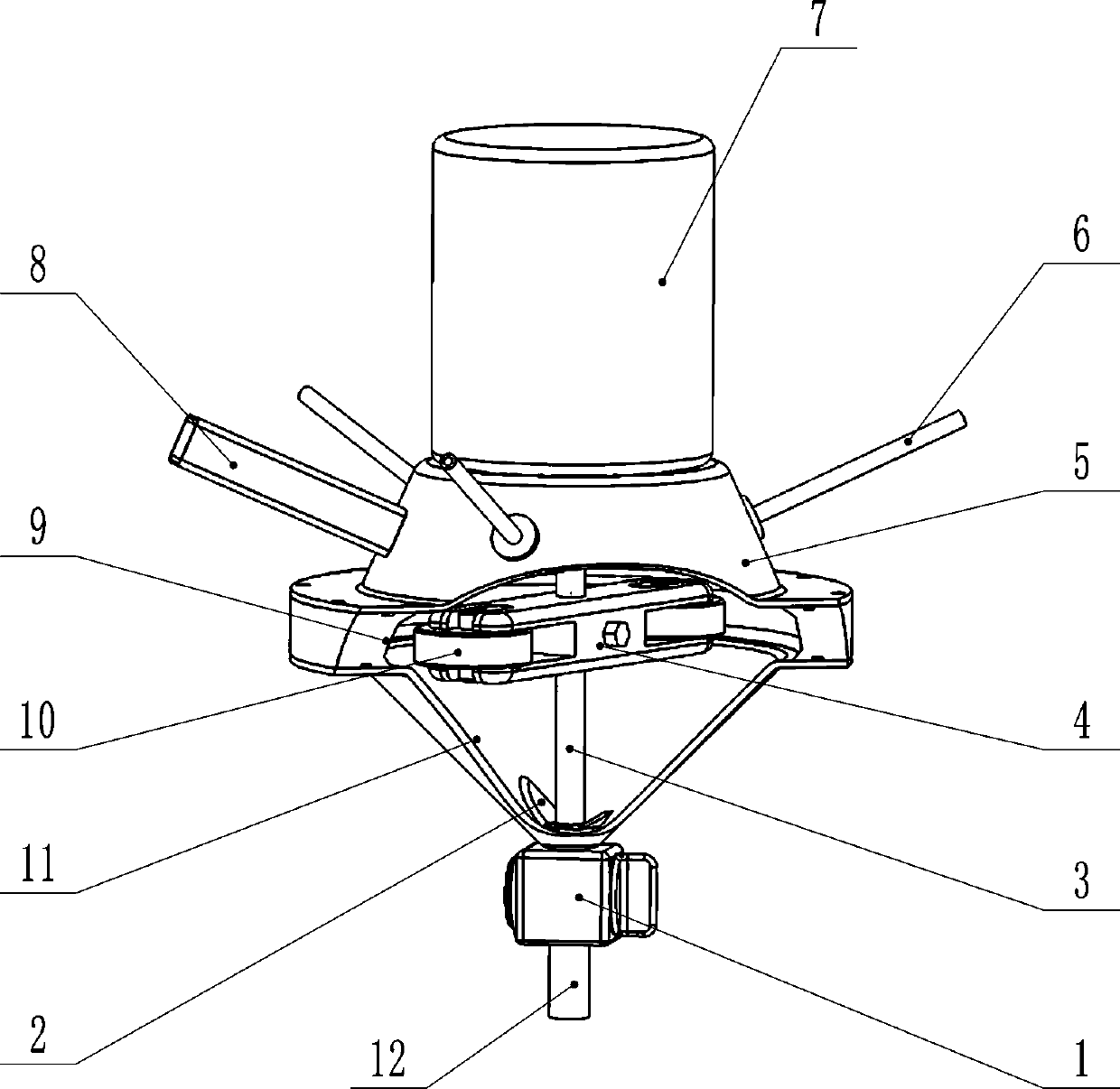
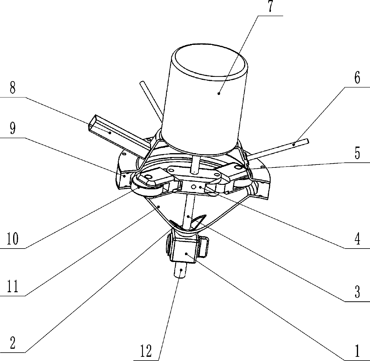
[0029] Such as figure 1 and figure 2 As shown, a rolling crushing machine includes a motor 7 and a main body of the breaking machine. The main body of the breaking machine is provided with a crushing cavity, and the crushing cavity includes a conical cutting cavity 11 at the lower part and a horizontal cutting cavity at the middle part. Ring groove type grinding chamber 9, the output shaft 3 of the motor 7 is longitudinally arranged in the crushing chamber, the output shaft 3 in the chopping chamber 11 is partially equipped with a crushing blade 2, and the output shaft in the grinding chamber 9 The shaft 3 part is equipped with a roller centrifugal frame 4, and two symmetrical grinding wheels 10 are installed on the outer end of the roller centrifugal frame 4. When the output shaft of the motor 7 rotates at a high speed, the grinding wheel 10 is under centrifugal force. Walk in the grinding chamber 9 of the horizontal ring groove type; the main body of the wall breaker is pr...

Embodiment 2

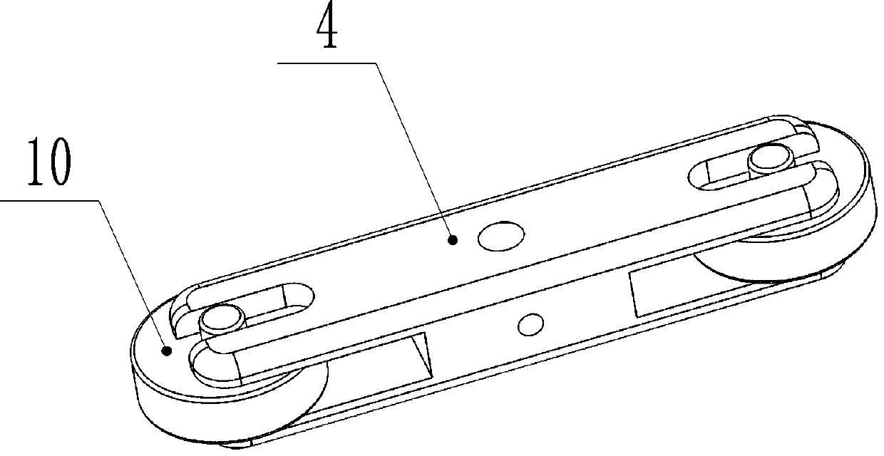
[0038] Such as image 3 and Figure 4 As shown, the difference from Embodiment 1 is that the roller centrifuge rack includes a base 4 and a roller arm 13 hinged on the base, the roller 10 is mounted on the roller arm 13, and the base 4 fixed on the output shaft 3.

[0039] This structure form is another kind of centrifugal structure, and the roller is less restricted.

Embodiment 3

[0041] Such as Figure 5-Figure 8 As shown, the difference from Embodiment 1 and Embodiment 2 is that the roller 10 is a gear, and the groove wall of the grinding chamber is a tooth groove 14 matched with the roller. Under the tooth structure, the rolling direction is more diverse and complicated, so as to avoid some hard and smooth particles from collapsing and flying in the process of rolling in a single direction, which has never been processed.


PUM


Abstract

The invention provides a rolling high speed blender. The rolling high speed blender comprises a motor and a high speed blender main body, wherein a crushing cavity is formed in the high speed blendermain body and comprises a cutting cavity with a conical lower part and a grinding cavity with a horizontal annular groove type in the middle; an output shaft of the motor is longitudinally arranged inthe crushing cavity; a part, in the cutting cavity, of the output shaft is provided with meshing blades; a part, in the grinding cavity, of the output shaft is provided with a roller centrifugal machine frame; a grinding wheel capable of moving in the radial direction is arranged at the outer end of the roller centrifugal machine frame; the output shaft of the motor drives the grinding wheel to do circular motion by taking output shaft of the motor as the axis; the grinding wheel travels in the horizontal annular groove type grinding cavity under the centrifugal force and rolls in the grinding cavity; and a feeding and discharging structure is arranged on the high speed blender main body. According to the rolling high speed blender, due to the fact that the centrifugal force generated bythe circular motion of the grinding wheel is converted into the grinding pressure on foods so as to crush food cells, the efficiency is higher, and the crushed food is fine and smooth.

Description

technical field [0001] The invention relates to a food processing tool, in particular to a rolling and breaking machine. Background technique [0002] In order to better digest food and facilitate the absorption of nutrients, or to crush fruit to obtain juice, a roller crusher is usually used to break the food cells. [0003] The current roller crusher is roughly divided into two types, one is to put the food in the cup of the roller crusher to cut the cells through the high-speed rotating blade, and the other is to crush the cell wall by impact , so as to achieve the destruction of the food cell wall. [0004] This method of destroying the cell wall by cutting or impacting the blade, because the action areas of the blade and the impact are lines and points respectively, the force is sufficient, but the effective area is too small, and the food treatment is not sufficient, resulting in low processing efficiency and broken pieces. The food is not delicate enough. Due to the...

Claims


Application Information

Patent Timeline
IPC IPC(8): B02C21/00B02C18/10B02C15/08
CPCB02C21/00B02C18/10B02C15/08
Inventor 卢振江卢兆焓
Owner HENAN BROTHER TECH DEV CO LTD
Why Eureka
Try Eureka