Circulating fluidized bed flue gas purification system and integrated connecting device thereof

A flue gas purification system, circulating fluidized bed technology, applied in gas treatment, chemical instruments and methods, separation methods, etc., can solve the problems of large space, limited space, no space for space, etc. The effect of overall space occupation, increased possibility, and shortened arrangement distance

Pending Publication Date: 2019-11-22
FUJIAN LONGKING DSDN ENGINEERING CO LTD
View PDF0 Cites 0 Cited by
  • Summary
  • Abstract
  • Description
  • Claims
  • Application Information

AI Technical Summary

Problems solved by technology

[0005] like figure 1 As shown, in the prior art, a bag filter 01 and a flue 02 are communicated between the desulfurization reaction tower 03 and the denitrification reaction tower 04, and the front end of the flue 02 (the end toward the upstream of the air flow) is connected with the bag filter 01 from the side of the bag filter 01. The wall communicates with the air outlet cavity 011 in the bag filter 01, then turns downwards and heats the flue gas inside to make it reach the temperature of the flue gas required by the denitrification reaction tower 04, and this setting can make the flue 02 in the bag filter Three horizontal sections 021 and two vertical sections 022 are formed between the dust collector 01 and the denitration reaction tower 04, and there is a turning point between two adjacent horizontal sections 021 and vertical sections 022, occupying a relatively small space Big
However, in practical engineering applications, compact factory areas are often encountered, the site is extremely limited, and there is no space for each system to be arranged in sequence, and it is impossible to arrange a complete flue gas purification system

Method used


Image

  • Circulating fluidized bed flue gas purification system and integrated connecting device thereof
  • Circulating fluidized bed flue gas purification system and integrated connecting device thereof
  • Circulating fluidized bed flue gas purification system and integrated connecting device thereof

Examples


Embodiment Construction

[0028] In order to enable those skilled in the art to better understand the technical solutions of the present invention, the present invention will be further described in detail below in conjunction with the accompanying drawings and specific embodiments.

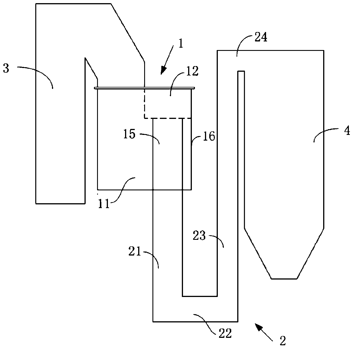
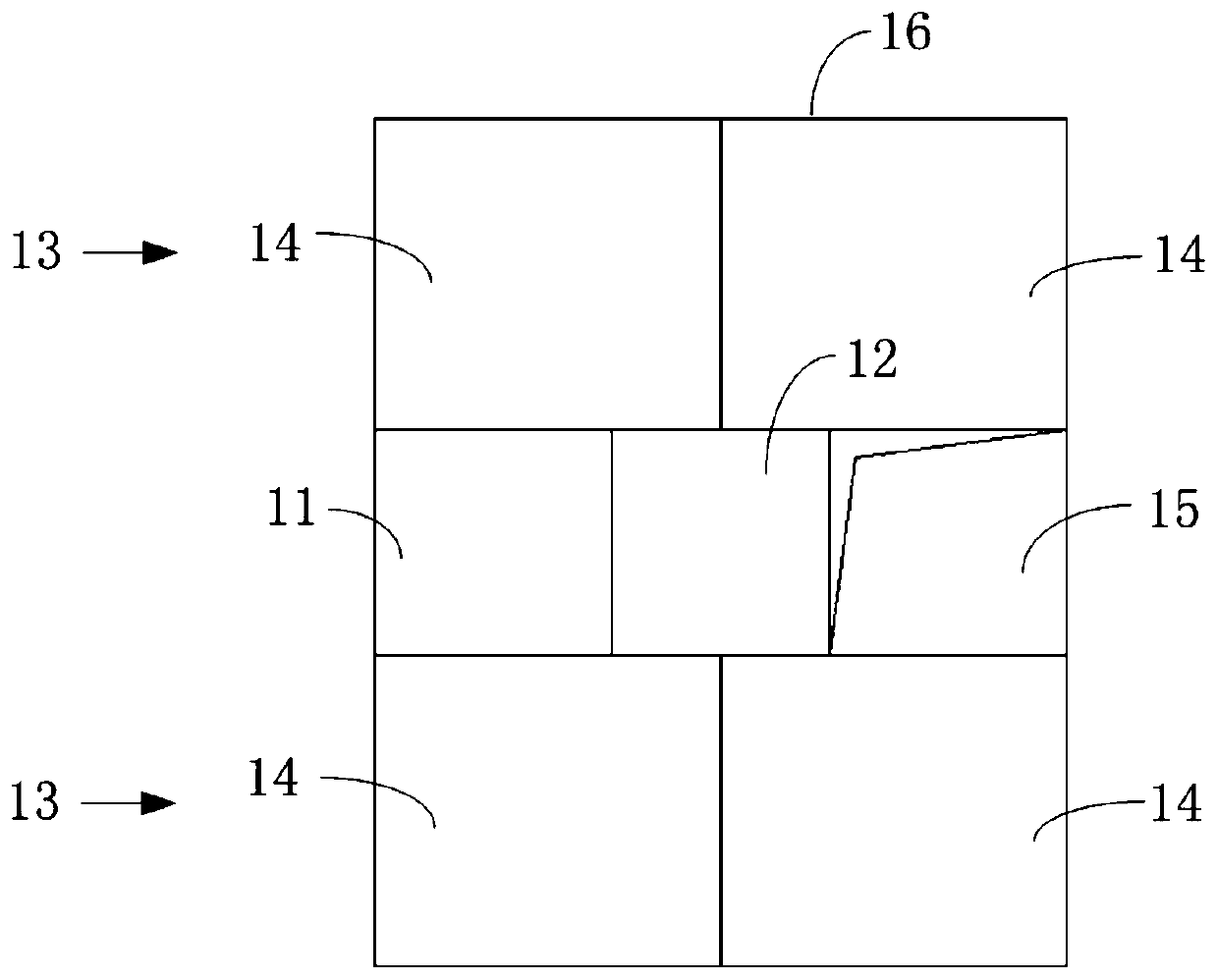
[0029] Please refer to Figure 2-3 , figure 2 It is a structural schematic diagram of a circulating fluidized bed flue gas purification system provided by an embodiment of the present invention; image 3 yes figure 2 The top view of the bag filter.

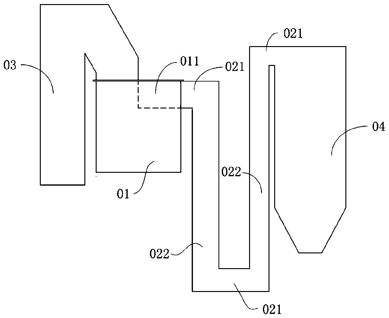
[0030] The embodiment of the present invention provides a circulating fluidized bed flue gas purification system and its integrated connection device, such as figure 2 As shown, the circulating fluidized bed flue gas purification system includes a desulfurization reaction tower 3, a denitrification reaction tower 4 and the above-mentioned integrated connecting device, wherein the integrated connecting device includes a bag filter 1 and a flue 2, and the bag filter 1 Th...


PUM


Abstract

The invention relates to a circulating fluidized bed flue gas purification system and an integrated connecting device thereof, and the integrated connecting device comprises a bag-type dust collectorand a flue; wherein a gas inlet is formed in the top end of the bag-type dust collector, a gas outlet is formed in the bottom end of the bag-type dust collector, the gas inlet is communicated with a gas outlet of a desulfurization reaction tower of the circulating fluidized bed method flue gas purification system, and the gas outlet is communicated with a denitration reaction tower of the circulating fluidized bed method flue gas purification system through a flue; the front end of the flue is communicated with the gas outlet in the vertical direction, so that the overall occupied space of thecirculating fluidized bed method flue gas purification system can be reduced. According to the invention, the overall arrangement possibility of the circulating fluidized bed method flue gas purification system is improved in a limited site space, and the flue gas emission requirement is satisfied.

Description

technical field [0001] The invention relates to the technical field of flue gas equipment, in particular to a circulating fluidized bed flue gas purification system and an integrated connection device thereof. Background technique [0002] The circulating fluidized bed flue gas purification system is composed of desulfurization reaction tower, bag filter, denitrification reaction tower, material circulation system, absorbent preparation and supply system, flue gas system, process water system, fluidization air system and other systems. The main process production equipment and auxiliary facilities are arranged around the desulfurization reaction tower and arranged in a centralized manner according to the process requirements. Among them, the desulfurization reaction tower, bag filter and denitration reaction tower are arranged in sequence. [0003] The outlet flue gas of the desulfurization reaction tower is filtered by the bag filter and enters the denitrification reaction ...

Claims


Application Information

Patent Timeline
IPC IPC(8): B01D46/02B01D46/42B01D53/75B01D53/56B01D53/48
CPCB01D46/0041B01D46/0047B01D46/023B01D53/75B01D53/56B01D53/48B01D2258/0283
Inventor 张原曹新秀陈旭荣李勇彬林志强初琨郭厚焜赖毅强林春源王建春
Owner FUJIAN LONGKING DSDN ENGINEERING CO LTD
Why Eureka
Try Eureka