
Engine fault detection device during automobile starting

A technology for fault detection and car startup, applied in the direction of internal combustion engine testing, etc., can solve problems such as affecting the driving safety of the car, affecting the driving of the car, difficult to detect, etc., to achieve the effect of easy intuitive judgment, reduced overall occupied space, and easy storage.

Active Publication Date: 2019-08-27
ARMY MILITARY TRANSPORTATION UNIV
View PDF6 Cites 0 Cited by
  • Summary
  • Abstract
  • Description
  • Claims
  • Application Information

AI Technical Summary

Problems solved by technology

[0005] Engine failures are more common and can be divided into several types. When the vehicle is driving, the engine will run. When the car goes uphill, if the engine power is insufficient, it will cause the car to vibrate, which will Affect the driving of the car. If the power of the engine is insufficient, the car may idling, which will easily affect the driving safety of the car. When the engine fails, it is difficult to visually judge the degree of car shaking when the body shakes. And then it is not easy to detect the condition of the engine. Existing methods generally detect the engine when the vehicle is not running, and it is difficult to simulate the impact of the vehicle on the engine when the vehicle is running. Therefore, it is necessary to design a vehicle Engine failure detection device when starting to solve the deficiencies in the prior art

Method used


Image

  • Engine fault detection device during automobile starting
  • Engine fault detection device during automobile starting
  • Engine fault detection device during automobile starting

Examples


Embodiment Construction

[0029] The following will clearly and completely describe the technical solutions in the embodiments of the present invention with reference to the accompanying drawings in the embodiments of the present invention. Obviously, the described embodiments are only some, not all, embodiments of the present invention. Based on the embodiments of the present invention, all other embodiments obtained by persons of ordinary skill in the art without making creative efforts belong to the protection scope of the present invention.

[0030] see Figure 1-4 , the present invention provides a technical solution:

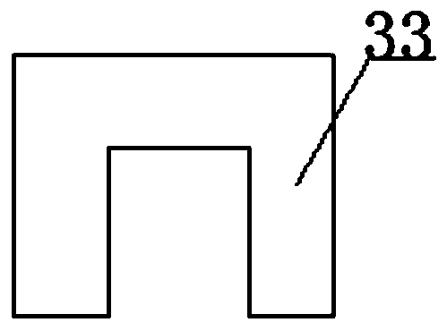
[0031] An engine fault detection device when a car is started, comprising a first bottom plate 23, a second bottom plate 34 and a turntable 25, the first bottom plate 23 and the second bottom plate 34 are pasted with a friction layer 30, the first bottom plate 23 and the second bottom plate Two bottom plates 34 are connected with stay cord 28 between the turntable 25, the fifth ro...


PUM


Abstract

The invention aims at solving a problem that a fault condition of an engine is not liable to visually judge at present, and discloses an engine fault detection device during automobile starting. The device comprises a connecting rod, a universal rod, a sliding pipe, a sliding frame, a spiral spring, a positioning disc, a positioning rod, a vibration measurer, a contact plate, a first rotating cylinder, a first rotating shaft, a first supporting rod, an ejector rod, a top plate, a conveying belt, a second rotating cylinder, a second rotating shaft, a second supporting rod, a first rotating plate, a third rotating shaft, a rotating rod, a fourth rotating shaft, a first bottom plate, a second rotating plate, a rotating disc, a fifth rotating shaft, a rocking handle, a pulling rope, a supporting plate, a friction layer, a hydraulic cylinder, a sixth rotating shaft, a rotating block and a second bottom plate. According to the device, two front wheels of the device are respectively placed onthe conveying belt through split design of the two bottom plates, and through inclined control of the supporting plate, the condition of the engine can be conveniently detected when the automobile runs on the slope; and furthermore, the device is reasonable in design and easy to operate and conforms to the social needs.

Description

technical field [0001] The invention relates to the field of automobile engine detection, in particular to an engine failure detection device when the automobile is started. Background technique [0002] Front-wheel drive refers to the power distribution method in which the engine only drives a pair of front wheels in car design. Today, most cars are equipped with front-wheel drive. In the early days of automobile development, rear-wheel drive designs were more common. On a front-wheel-drive car, the engine is generally installed horizontally, that is, the cylinder arrangement direction is perpendicular to the running direction of the car, but there are also a few models where the engine is installed longitudinally. Front-wheel drive vehicles usually have the engine and transmission at the front of the car as well. [0003] Car failure is the phenomenon that the car cannot complete its function, such as difficulty in starting the engine, failure to start the car, oil leak...

Claims


Application Information

Patent Timeline
IPC IPC(8): G01M15/12
CPCG01M15/12
Inventor 夏均忠郑建波袁沐潘世举杨刚刚白云川
Owner ARMY MILITARY TRANSPORTATION UNIV
Learn More