Tower grounding resistance measuring method based on ground surface voltage

A technology of grounding resistance and measurement method, which is applied in the field of power system, can solve the problems of long pole layout distance, large measurement error, and large extension range, so as to improve measurement efficiency and measurement accuracy, reduce measurement workload, and ensure The effect of measurement accuracy

Active Publication Date: 2019-05-21
CHONGQING UNIV
View PDF6 Cites 1 Cited by
  • Summary
  • Abstract
  • Description
  • Claims
  • Application Information

AI Technical Summary

Problems solved by technology

The three-pole method has the advantage of high measurement accuracy, but the biggest defect of the three-pole method is that it needs to arrange a long current lead (in engineering, it is generally required that the voltage pole reaches 2.5 times the scattering length of the horizontal ground body, and the corresponding current pole distance is It needs to reach 4 times the length of the scattering horizontal grounding body), and the grounding device of the mountainous line often needs a longer grounding body ray length due to the high soil resistivity, the extension range is large, and the terrain is complex, so a longer current lead wire layout is required polar distance
However, when measuring with the three-pole method, all grounding leads of the tower must be disconnected, and the layout is easily restricted by the terrain of the tower, and the distance between the poles is relatively long; ③The high-frequency parallel connection method realizes the grounding resistance value of the tower without disconnecting the grounding leads. However, this method only considers the resistance value of the grounding resistance of the tower when the model is established, and in the case of high soil resistivity or the injection of high-frequency current, the inductance effect needs to be considered, and the measurement error is relatively large; ④ The biggest advantage of the clamp meter method is that there is no need to arrange electrodes during measurement, as long as the clamp meter is clamped on the grounding lead, the measurement can be carried out, but the measurement accuracy of this method is low, and it is difficult to meet the actual requirements of the project
[0005] Among the existing grounding resistance measurement methods, only the pole layout measurement method has high accuracy, and the existing pole layout measurement ground resistance methods all have the huge defect that a long distance of measurement leads needs to be laid outside the tower base or outside the grounding grid. Although the pole method reduces the distance between the poles to a certain extent, the length of the measurement lead cannot meet the engineering requirements, and the number of poles is large. These measurement methods are difficult to use in areas with limited poles such as mountains and cities. At the same time, it is necessary to disconnect the grounding down conductor, which will cost a lot of labor
However, if the measurement method of not disconnecting the grounding down-conductor is adopted, the measured grounding resistance is difficult to meet the measurement accuracy requirements.
Therefore, there is an urgent need for a pole layout measurement method with a short pole layout distance and no need to disconnect the grounding down-conductor, so as to improve the measurement accuracy and measurement efficiency of the measurement method, and at the same time solve the problem that the long measurement lead wire measurement method is limited by the terrain

Method used


Image

  • Tower grounding resistance measuring method based on ground surface voltage
  • Tower grounding resistance measuring method based on ground surface voltage
  • Tower grounding resistance measuring method based on ground surface voltage

Examples


Embodiment Construction

[0025] The present invention will be further described below in conjunction with the accompanying drawings of the description.

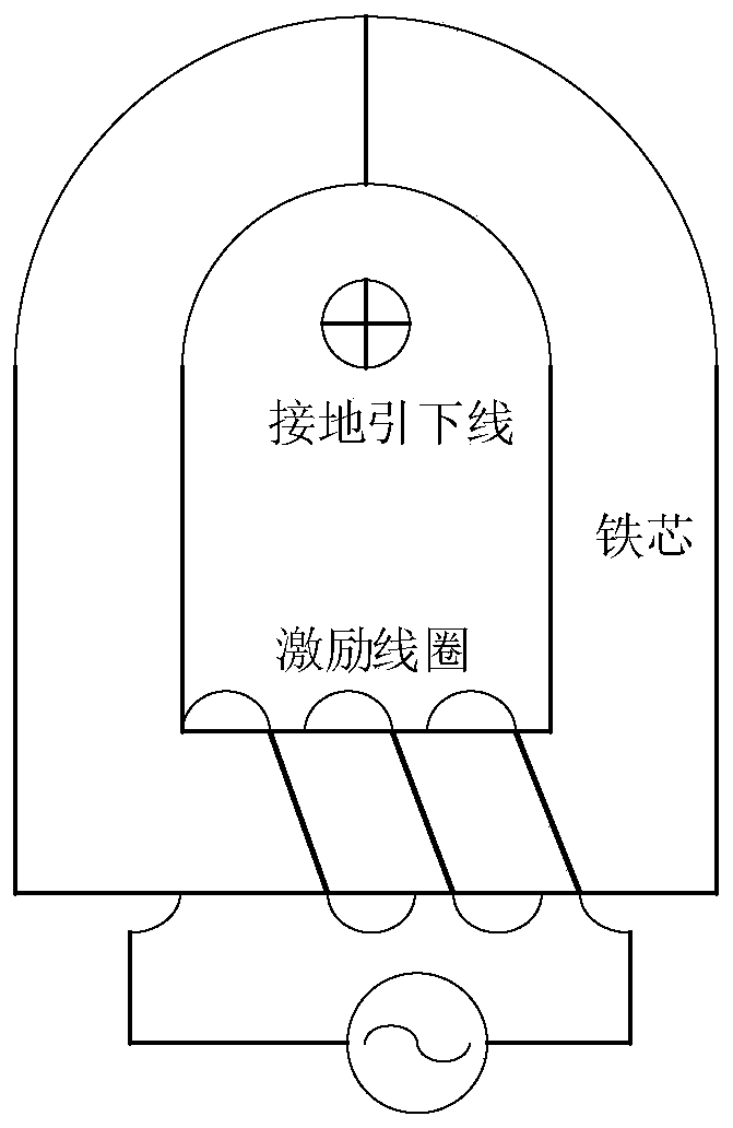
[0026] (1) see figure 1 : Generation of grounding down conductor current

[0027] Clamp the ring-shaped iron core with the exciting coil around the tower grounding down conductor, so that the turns are connected to the grounding down conductor. closed loop. The excitation coil is wound on one side of the annular iron core, thereby forming a step-down transformer with the coil side as the primary side and the grounding downconductor side as the secondary side. When an AC voltage is applied to both ends of the excitation coil of the annular iron core, an induced electromotive force will be formed on the closed loop between the grounding downconductor of the tower under test, the transmission line, the grounding downconductor of the adjacent tower and the ground, thereby forming a grounding conductor. The induced current on the lower wire and drains ...


PUM


Abstract

The invention discloses a tower grounding resistance measuring method based on the ground surface voltage. An annular iron core with a power supply excitation coil senses an excitation current on a grounding lead of a transmission tower and an nnular iron core with a current receiving coil measures the current flowing through a grounding lead; the resistivity of the soil is obtained by using a potential distribution relationship at a long distance to a grounding body on the ground surface and thus the voltage of the grounding body is measured and calculated; and then a grounding resistance value is finally measured. According to the invention, the advantages of avoiding disconnection of a ground lead down wire of the clamp meter method and having the high measurement precision of the traditional three-pole method are combined fully, so that defects of low measurement precision and long pole arrangement distance of the conventional measurement method are overcome; the measurement efficiency and measurement accuracy of the grounding resistance are improved substantially; and a practical measurement method is provided for measuring the grounding resistance of the tower.

Description

technical field [0001] The invention belongs to the field of power systems, in particular to a method for measuring grounding resistance of towers based on earth surface voltage. Background technique [0002] Grounding resistance measurement is a necessary means for diagnosing the corrosion of the grounding body of the tower and checking whether the grounding device meets the requirements of the regulations. Accurate measurement of grounding resistance can verify the safety of the grounding system, discover changes or defects in the grounding system in time, and avoid economic losses or accidents that may be caused by unqualified grounding. [0003] In the traditional grounding resistance measurement methods, the three-pole method of disconnecting the grounding down-conductor and the clamp meter method of not disconnecting the grounding down-conductor are the main methods. The three-pole method has the advantage of high measurement accuracy, but the biggest defect of the th...

Claims


Application Information

Patent Timeline
IPC IPC(8): G01R27/20
Inventor 张占龙高成烽旦乙画邹静
Owner CHONGQING UNIV
Why Eureka
Try Eureka