
A Multifunctional Electret Generator Based on Permanent Magnetic Levitation Gyro

A magnetic levitation gyroscope and electret technology, applied in induction generators, triboelectric generators and other directions, can solve the problems of low vibration wind speed, small contact area, easy damage of surface nanostructures, etc., to overcome stress concentration, increase Vibration frequency bandwidth, effect of increasing the rate of change of intrinsic capacitance

Active Publication Date: 2021-01-05
NORTHWESTERN POLYTECHNICAL UNIV
View PDF4 Cites 0 Cited by
  • Summary
  • Abstract
  • Description
  • Claims
  • Application Information

AI Technical Summary

Problems solved by technology

However, this generator can only rely on the rotating shaft to drive the friction of fibers to generate energy. Under the same volume, the contact area is small, and after long-term repeated friction, the surface nanostructure is easily damaged, and the lowest starting wind speed is too high.

Method used


Image

  • A Multifunctional Electret Generator Based on Permanent Magnetic Levitation Gyro
  • A Multifunctional Electret Generator Based on Permanent Magnetic Levitation Gyro
  • A Multifunctional Electret Generator Based on Permanent Magnetic Levitation Gyro

Examples


Embodiment 1

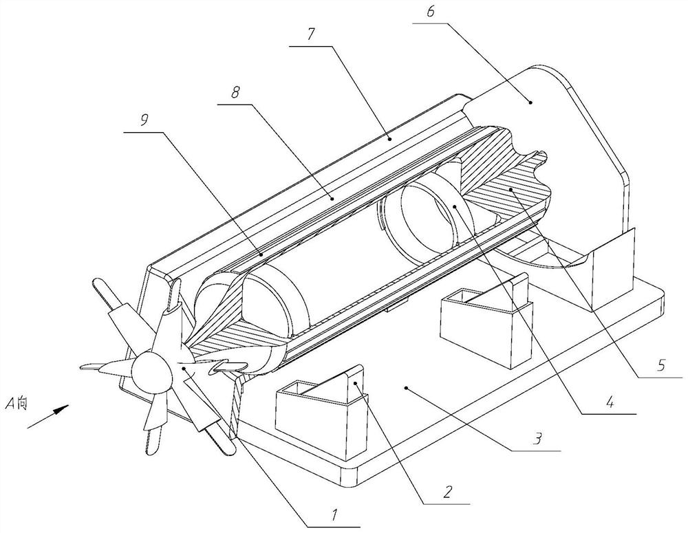
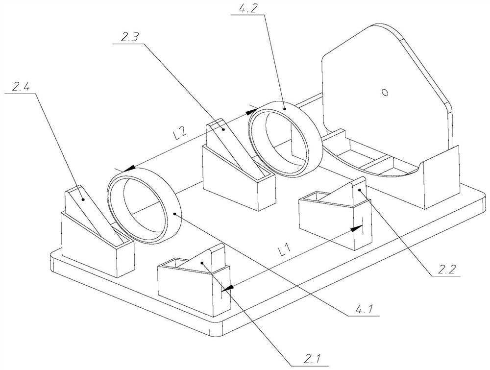
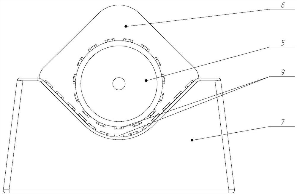
[0035] Such as Picture 1-1 As shown, the essence of this embodiment is a variable capacitor that utilizes an electret to provide a bias voltage. The multifunctional electret generator of the permanent magnetic levitation gyroscope mainly includes a blade rotor 1, a triangular permanent magnet 2, an insulating substrate 3, a ring Permanent magnet 4, vibration pickup rotor 5, positioning block 6, fixed magnet cover 7, substrate electrode 8 and electret polymer film 9, wherein: insulating substrate 3, fixed magnet cover 7, vibration pickup rotor 5 from bottom to bottom Arranged in sequence on the top, the positioning block 6 is inserted into the groove at the corresponding position of the insulating substrate. The structure composed of the triangular permanent magnet 2, the insulating substrate 3, the positioning block 6 and the fixed magnet cover 7 according to the assembly sequence is called an external fixed component. The structure composed of the blade rotor 1, the vibratio...

Embodiment 2

[0047] A multifunctional electret energy harvester composed of upper and lower external fixed components

[0048] Such as figure 2 As shown, it is a multi-functional electret energy harvester composed of upper and lower external fixed components, and the rest of the structural principle is the same as that of embodiment 1, and a triangular permanent magnet 2 of the same size is installed on the upper insulating substrate 3 , the polarity selection is the same as in Example 1. In this way, the two external fixed components can make the operation of the vibration pickup rotor assembly more stable. At the same time, because the two fixed substrate electrodes 8 output electric energy at the same time, the output electric energy is further increased, and the outer cylindrical surface of the vibration pickup rotor 5 is fully utilized. The electret thin film material makes it rotate in the same revolution and the power generation is twice that of Example 1.

Embodiment 3

[0050] Such as image 3 As shown, in this example, the blade rotor 1 that bears wind force is replaced with blades that can receive wind and collect hydraulic energy, which further broadens the form of energy collection and expands the application occasions of the generator.

[0051] The hydraulic collecting blade 1 is composed of 6 bowl-shaped blades, the diameter of the part bearing the wind force is 16mm, and the length is 28mm.


PUM


Abstract

A multifunctional electret generator based on a permanent magnetic suspension gyroscope includes a vibration pickup rotor component and an external fixed component. A structure formed by assembling atriangular permanent magnet, an insulating substrate, a positioning baffle, and a fixing magnet cover in accordance with an assembly order is called the external fixed component. A structure formed byassembling a blade rotor, a vibration pickup rotor, and two annular permanent magnets in accordance with an assembly order is called the vibration pickup rotor component. By adjusting the positions of the triangular permanent magnet and the annular magnets, the vibration pickup rotor component can be suspended over the external fixed component under the point contact limitation of the positioningbaffle. By using the power generation principle of the electret film electrostatic induction, charges are injected into an electret film so as to generate a bias voltage on a substrate electrode covered by the vibration pickup rotor, thereby outputting AC power to an external circuit. Mechanical vibration energy, wind energy and hydraulic energy are converted into electric energy. The multifunctional electret generator has good output characteristics, a simple structure, low damping, a wide frequency band, and excellent durability and dexterity.

Description

technical field [0001] The invention belongs to the field of energy conversion of micro-energy systems, and in particular relates to a multifunctional electret generator based on a permanent magnetic levitation gyroscope. Background technique [0002] With the wide application of wireless sensor networks in portable electronic products and other fields, its devices require a relatively long service life and are widely distributed. It is impractical to replace batteries or use power line power supply, which poses new challenges to the power supply of devices. challenge. At present, the energy consumption of micro wireless products and MEMS devices has been reduced to the milliwatt level, which makes it possible to convert mechanical vibration energy, hydropower energy and wind energy in the environment into electrical energy, and then drive the work of micro devices. [0003] However, several issues need to be resolved before the energy harvesting technology can be practical...

Claims


Application Information

Patent Timeline
Patent Type & Authority Patents(China)
IPC IPC(8): H02N1/04H02N1/08
CPCH02N1/04H02N1/08
Inventor 陶凯易海平王一炜杨扬张瑞荣申强常洪龙
Owner NORTHWESTERN POLYTECHNICAL UNIV
Learn More