
System and method for automatic scanning of target objects

An automatic scanning and target object technology, applied in the field of building information modeling, can solve the problems of not providing a fully automatic solution for the scanning area of ​​interest, unable to solve the boundary problem of the object of interest and noise, etc., to ensure full automation and accuracy performance, the effect of ensuring accuracy

Inactive Publication Date: 2020-04-24
吕若丹
View PDF5 Cites 0 Cited by
  • Summary
  • Abstract
  • Description
  • Claims
  • Application Information

AI Technical Summary

Problems solved by technology

[0005] As far as the inventor understands, current scanner hardware devices only provide artificially assisted methods to customize the designated scanning area
At the same time, the existing scanner hardware and supporting software do not provide a fully automatic solution for detecting the scanning area of ​​interest in the point cloud scanning and preprocessing stages, and cannot solve the boundary problem and noise problem of accurately depicting the object of interest

Method used


Image

  • System and method for automatic scanning of target objects
  • System and method for automatic scanning of target objects
  • System and method for automatic scanning of target objects

Examples


Embodiment Construction

[0060] The present disclosure will be further described below in conjunction with the accompanying drawings and embodiments.

[0061] It should be noted that the following detailed description is exemplary and intended to provide further explanation of the present disclosure. Unless defined otherwise, all technical and scientific terms used herein have the same meaning as commonly understood by one of ordinary skill in the art to which this disclosure belongs.

[0062] It should be noted that the terminology used herein is only for describing specific embodiments, and is not intended to limit the exemplary embodiments according to the present disclosure. As used herein, unless the context clearly dictates otherwise, the singular is intended to include the plural, and it should also be understood that when the terms "comprising" and / or "comprising" are used in this specification, they mean There are features, steps, operations, means, components and / or combinations thereof.

...


PUM


Abstract

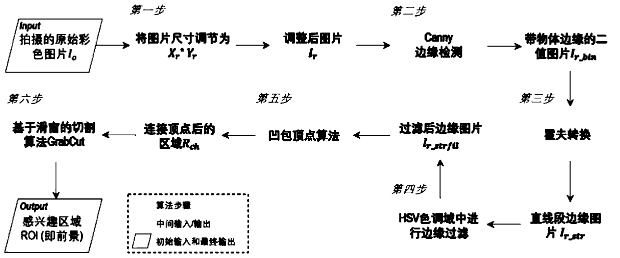
The invention provides a target object automatic scanning system and method, and the method comprises the steps: carrying out the processing of color images sequentially photographed in a scanner through a machine vision object detection algorithm to obtain an interested scanning region; establishing a mapping relationship between the picture pixel coordinates and the real world coordinates, and calculating the angle of the world coordinates corresponding to each pixel of the scanning area relative to the laser radar based on the mapping relationship; and constructing an angle sequence by taking the minimum angle and the maximum angle as boundaries, calculating corresponding points in a camera coordinate system according to the distances between the points in the sequence and scanned points in the scanning area and the laser radar, forming a scanning path, and controlling the action of the scanner according to the scanning path. According to the invention, the interested scanning areaand the corresponding scanning path can be automatically provided, and the effectiveness, accuracy and intelligence of the acquired image are ensured.

Description

technical field [0001] The disclosure belongs to the technical field of building information modeling, and in particular relates to an automatic scanning system and method for a target object. Background technique [0002] The statements in this section merely provide background information related to the present disclosure and do not necessarily constitute prior art. [0003] At present, building digital twinning technology (Digital Twinning) or building information modeling (Building Information Modeling) technology has been widely used in construction engineering fields such as monitoring, inspection, and management of infrastructure assets. Among them, it is a common practice to use laser point cloud data (PointClouds) to generate digital geometric twins (GeometricDigitalTwin abbreviated as gDT) of existing infrastructure, or building information geometric models (BIMmodel). However, it is worth noting that the process from point cloud to digital geometric twin (scan-to...

Claims


Application Information

Patent Timeline
Patent Type & Authority Patents(China)
IPC IPC(8): G06T7/13G06T5/30G06T7/90
CPCG06T5/30G06T7/13G06T7/90G06T2207/10024G06T2207/10028
Inventor 吕若丹刘建亚马悦宁郭亮
Owner 吕若丹
Learn More