
Calibration method for polarization laser radar

A technology of laser radar and calibration method, which is applied in the direction of re-radiation of electromagnetic waves, utilization of re-radiation, and measurement devices, which can solve the problems that the particle shape cannot be obtained through the data, it is difficult to do it, and there are errors, so as to achieve effective and accurate calibration The effect of work

Active Publication Date: 2019-11-19
NANJING UNIV OF INFORMATION SCI & TECH
View PDF9 Cites 2 Cited by
  • Summary
  • Abstract
  • Description
  • Claims
  • Application Information

AI Technical Summary

Problems solved by technology

[0005] If the calibration of the polarization lidar system is not carried out, even if the polarization lidar is used to measure the atmosphere to obtain corresponding data, the shape of the detected particles cannot be obtained from the data
On the other hand, if the calibration work is not done well, there will be errors in the calibration results, which will affect the inversion accuracy of the polarization lidar
[0006] At present, there are many methods for polarized lidar calibration. V. Freudenthaler et al. proposed that the calibration process of lidar can be completed by placing a half-wave plate in front of the polarizing beam splitter and rotating the half-wave plate. Bu Lingbing et al. proposed that based on the Jones matrix To calibrate the polarization constant of the lidar, these methods need to adjust the main axis of the half-wave plate to be parallel to the polarization plane of the polarizing beam splitter, which is very difficult to achieve in actual operation

Method used


Image

  • Calibration method for polarization laser radar
  • Calibration method for polarization laser radar
  • Calibration method for polarization laser radar

Examples


Embodiment Construction

[0025] The invention will be described in further detail below in conjunction with the accompanying drawings.

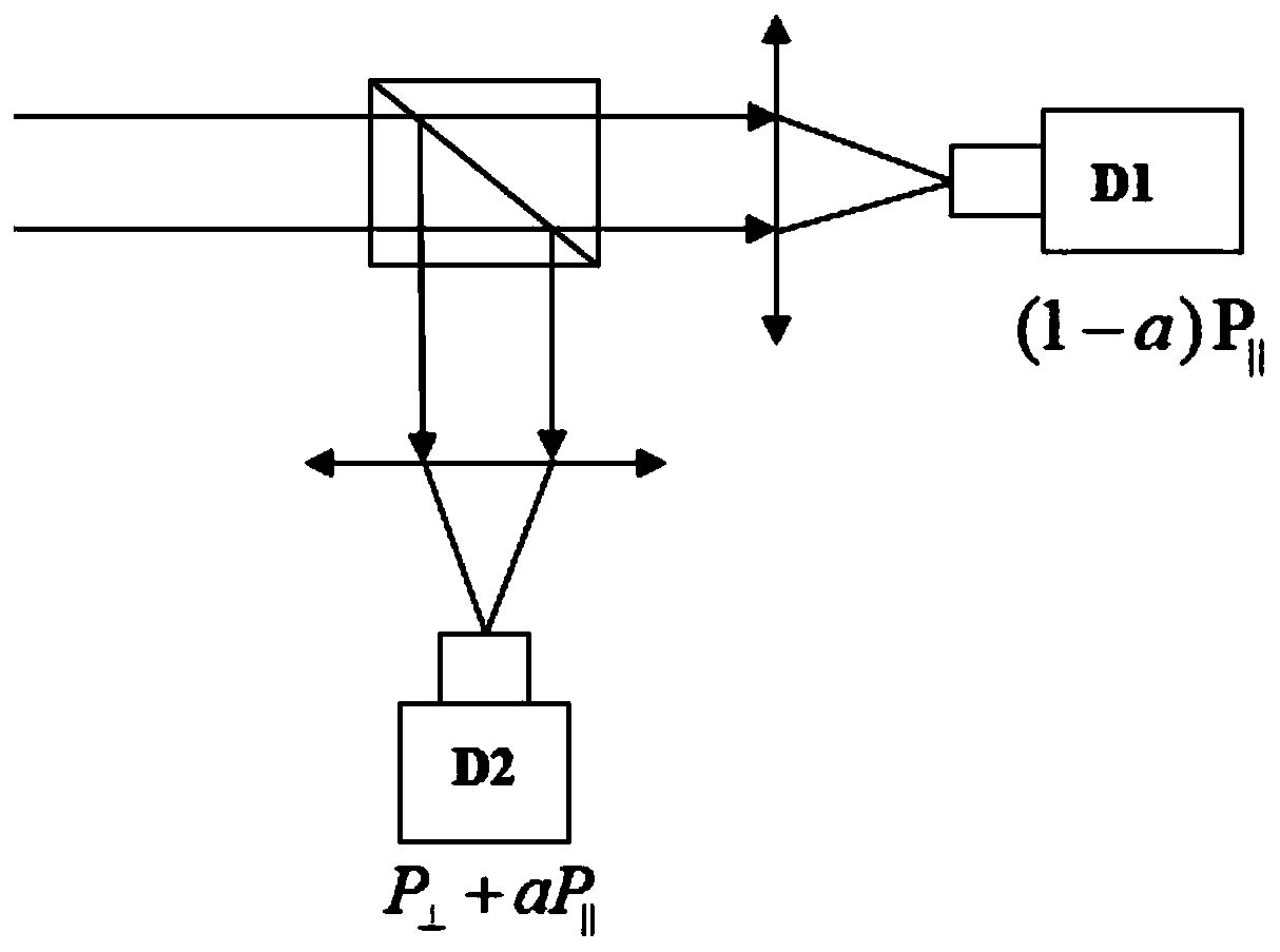
[0026] For the polarization laser radar system used in the calibration method, see figure 1 .

[0027] The calibrated polarization lidar system includes a transmitting system and a receiving system.

[0028] The launch system includes: laser, beam expander and reflector. The receiving system includes: telescope, pinhole, mirror, collimator, filter, polarizing beam splitter, parallel channel photomultiplier tube and vertical channel photomultiplier tube.

[0029] The invention proposes a calibration parameter that can be divided into a detector gain ratio and a laser radar light leakage ratio, and the two parameters are respectively solved by exchanging the photomultiplier tubes of the two channels. The calibration method is as follows: figure 2 As shown, the laser signal received by the lidar telescope enters the polarization beam splitter (PBS) after being filt...


PUM


Abstract

The invention discloses a calibration method for a polarization laser radar and belongs to the technical field of laser radar calibration. The calibration method for the polarization laser radar is based on the light leakage ratio of a polarization beam splitter (PBS). The calibration method is used for correcting the depolarization ratio of the polarization laser radar. According to the method, the photomultipliers of two channels are exchanged, depolarization ratios under two situations are calculated, so that the gain ratio G of the two photomultipliers is calculated; and the value of a light leakage ratio a is calculated according to the depolarization value of standard atmospheric molecules; and the gain ratio G and the light leakage ratio a are both system constants and will not change due to weather, so that the two calibration constants can be used for correcting a depolarization ratio in subsequent observation. With the method of the invention adopted, the calibration work ofthe polarization laser radar system can be effectively and accurately carried out.

Description

technical field [0001] The invention relates to a calibration method of a polarization laser radar, belonging to the technical field of laser radar calibration. Background technique [0002] According to the particle scattering theory, when the incident light and particles are scattered, the shape and size of the particles will change the polarization state of the scattered light. According to the polarization state of the echo signal, the shape of the atmospheric particles can be calculated, and the polarization laser radar can also be obtained. develop. [0003] As an effective tool for studying dust aerosols and cirrus clouds, polarized lidar, compared with ordinary rice scattering lidar, adds a polarization beam splitter to the detection system of the relay optical path, so that the optical signals orthogonal to each other in the electromagnetic field Divided into two beams of optical signals that are perpendicular to each other in space, and then detected by two photod...

Claims


Application Information

Patent Timeline
IPC IPC(8): G01S7/497G01S17/88G01S17/95
CPCG01S7/497G01S17/88G01S17/95Y02A90/10
Inventor 卜令兵谢佳明张衡衡
Owner NANJING UNIV OF INFORMATION SCI & TECH
Learn More