
Optical fiber birefringence effect-based time-resolved CARS microscopic imaging device and method

A microscopic imaging, time-resolved technology, applied in measurement devices, material analysis by optical means, Raman scattering, etc., can solve the problems of the use and development of time-resolved CARS microscopic imaging systems, and increase the complexity of the system's spatial optical path. Maintenance costs and other issues, to achieve the effect of eliminating external synchronization equipment, simple production methods, and reducing complexity

Active Publication Date: 2019-11-19
TIANJIN UNIV
View PDF6 Cites 0 Cited by
  • Summary
  • Abstract
  • Description
  • Claims
  • Application Information

AI Technical Summary

Problems solved by technology

In the commonly used time-resolved CARS microscopic imaging system, in order to generate the time delay between the pump light pulse and the probe light pulse, the method of adding a pump laser or adding a spatial optical delay line is usually used, which undoubtedly increases the space optical path of the system. The complexity and the cost of operation and maintenance are not conducive to the use and development of time-resolved CARS microscopy imaging system

Method used


Image

  • Optical fiber birefringence effect-based time-resolved CARS microscopic imaging device and method
  • Optical fiber birefringence effect-based time-resolved CARS microscopic imaging device and method
  • Optical fiber birefringence effect-based time-resolved CARS microscopic imaging device and method

Examples


Embodiment Construction

[0027] The technical solution of the present invention will be described in detail below in conjunction with the accompanying drawings and embodiments.

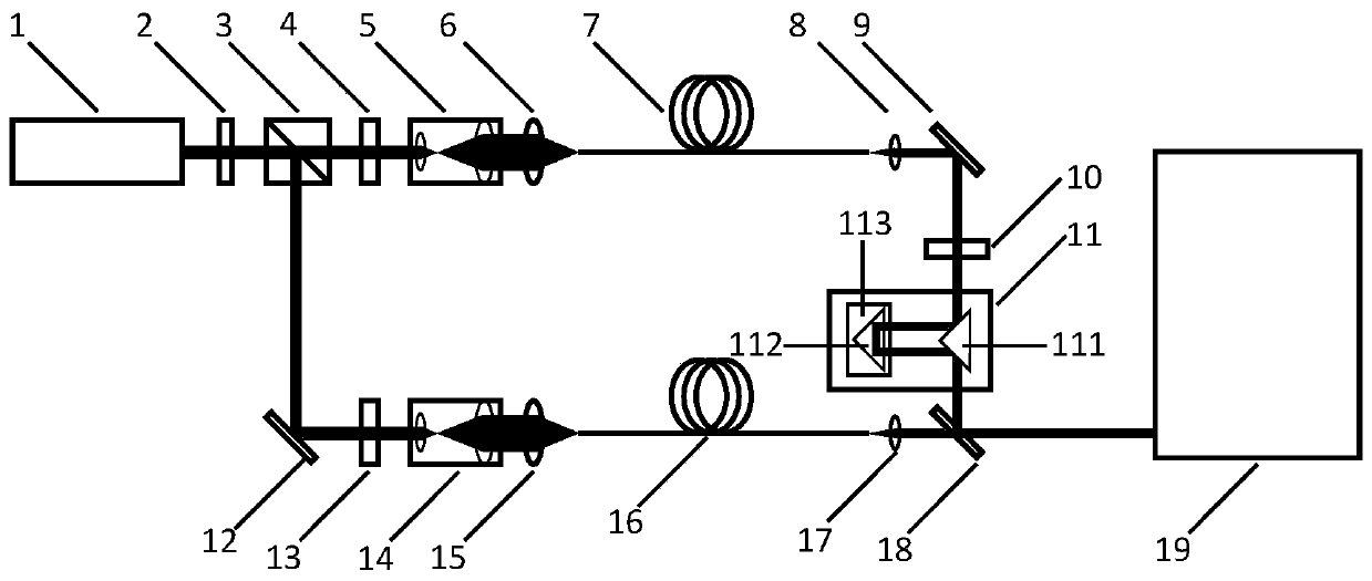
[0028] Such as figure 1 As shown, it is a structural schematic diagram of the time-resolved CARS microscopic imaging device based on the fiber birefringence effect of the present invention, the device consists of a femtosecond laser 1, a power adjustment part (made up of an electrically controlled liquid crystal wave plate 2, and a polarizing beam splitter prism 3) , the Stokes optical path part (made up of the first half-wave plate 4, the first beam expander 5, the first fiber coupling mirror 6 and the highly nonlinear polarization-maintaining photonic crystal fiber 7), the first optical fiber collimator Beam expander 8, first reflector 9, long-pass filter 10, adjustable spatial light delay line 11 (composed of first right-angle reflective prism 111, second right-angle reflective prism 112 and high-precision electronically c...


PUM


Abstract

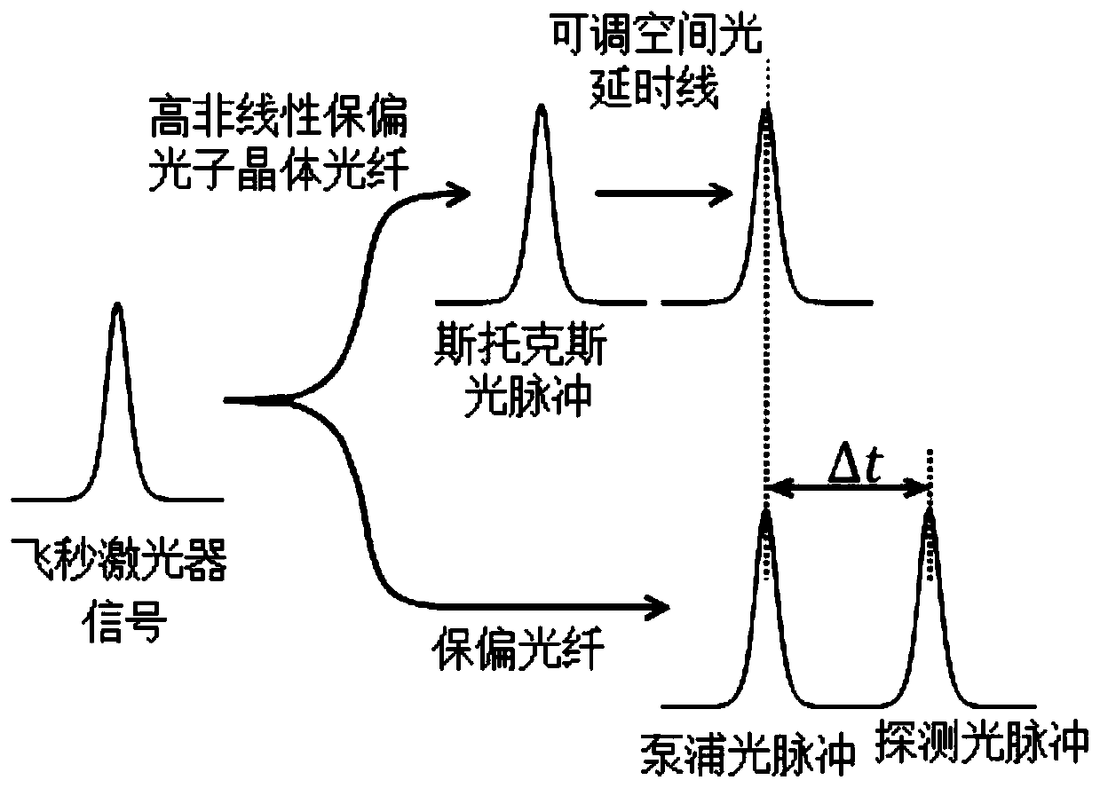
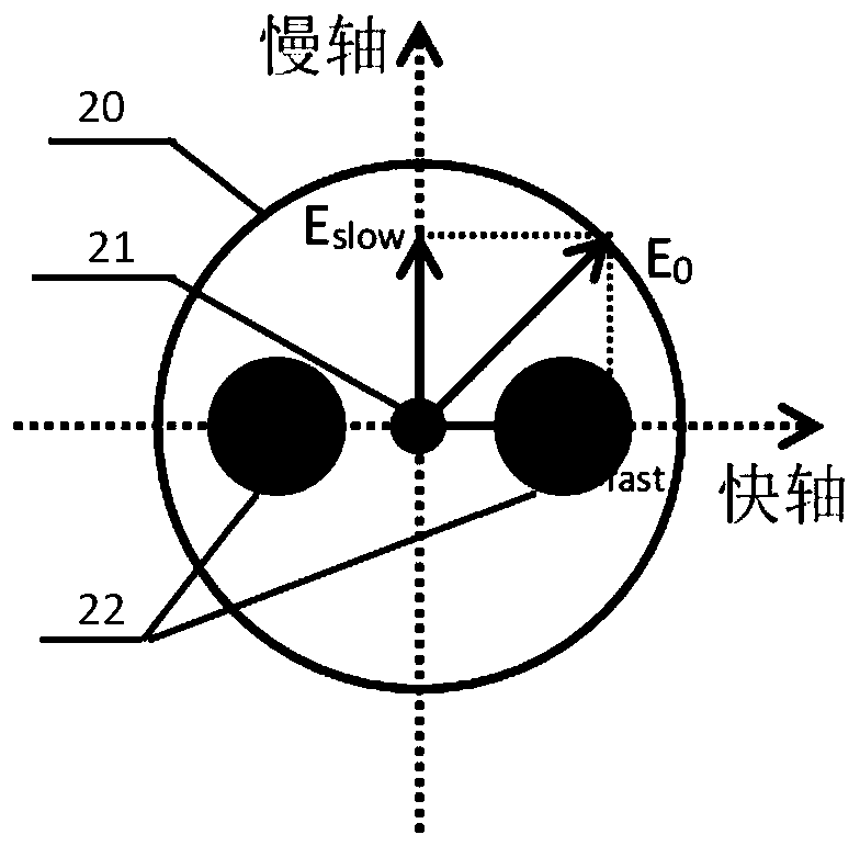
The invention discloses an optical fiber birefringence effect-based time-resolved CARS microscopic imaging device and method. The device at least comprises a femtosecond laser, a power adjusting part,a stokes light path part, a pump light pulse and detection light pulse light path part, a short-pass dichroscope and a CARS microscopic imaging system; a part of ultrashort pulses enter a polarization maintaining optical fiber along the angular bisector of the fast axis and slow axis of the polarization maintaining optical fiber; since the refractive indexes of the fast axis and slow axis of thepolarization maintaining optical fiber are different, the fast-axis optical pulses and slow-axis optical pulses of the output end of the polarization-maintaining optical fiber under relative time delay and are respectively used as pump light pulses and detection light pulses; the other part of the ultrashort pulses are inputted into a high-nonlinearity polarization-maintaining photonic crystal fiber; wavelength red-shift optical soliton pulses are generated through a soliton self-frequency shift effect; and the wavelength red-shift optical soliton pulses are used as stokes light pulses. With the optical fiber birefringence effect-based time-resolved CARS microscopic imaging device and method of the invention adopted, the measurement of time-resolved CARS signals is realized, and at the same time, the complexity of a traditional time-resolved CARS microscopic imaging system is reduced.

Description

technical field [0001] The invention belongs to the field of nonlinear optical fiber and spectral resonance microscopic imaging, in particular to a time-resolved CARS microscopic imaging device and method. Background technique [0002] CARS microscopic imaging technology is a label-free, non-contact and chemically selective microscopic imaging technology that uses the resonance energy level information of molecules in substances to perform resonance spectrum imaging. Its essence is pump light, probe light, and the resonance energy level of the sample to be measured The four-wave mixing effect, when the frequency difference between the pump light and the Stokes light is equal to the resonance energy level of the target chemical bond in the sample to be tested, and the three meet the phase matching conditions, the anti-Stokes of the sample to be tested will be excited X Raman scattering signal, that is, CARS signal. However, in the traditional CARS microscopic imaging system,...

Claims


Application Information

Patent Timeline
IPC IPC(8): G01N21/65G01N21/01
CPCG01N21/65G01N21/01
Inventor 江俊峰张永宁刘铁根刘琨王双张学智丁振扬
Owner TIANJIN UNIV
Learn More