
Self-tightening type steel wire clamp

A wire clamp, self-tightening technology, applied in the direction of transmission elements or pulley ropes or cables, textile cables, belts/chains/gears, etc., can solve the problem of wire waste and other problems

Pending Publication Date: 2019-11-19
BEIJING URBAN CONSTR EXPLORATION & SURVEYING DESIGN RES INST
View PDF0 Cites 0 Cited by
  • Summary
  • Abstract
  • Description
  • Claims
  • Application Information

AI Technical Summary

Problems solved by technology

[0003] Fixing the steel wire on the steel pipe after multiple turns of winding is easy to cause waste of steel wire; secondly, at least two people are required to complete it, one person winds the steel wire to fix it, and then another person is needed to help fix the horizontal steel pipe at the shaft mouth; third, If you need to adjust the position of the steel wire, you still need to use the help of others to move the position of the steel wire

Method used


Image

  • Self-tightening type steel wire clamp
  • Self-tightening type steel wire clamp
  • Self-tightening type steel wire clamp

Examples


Embodiment Construction

[0026] The following will clearly and completely describe the technical solutions in the embodiments of the present invention with reference to the accompanying drawings in the embodiments of the present invention. Obviously, the described embodiments are only some, not all, embodiments of the present invention. Based on the embodiments of the present invention, all other embodiments obtained by persons of ordinary skill in the art without making creative efforts belong to the protection scope of the present invention.

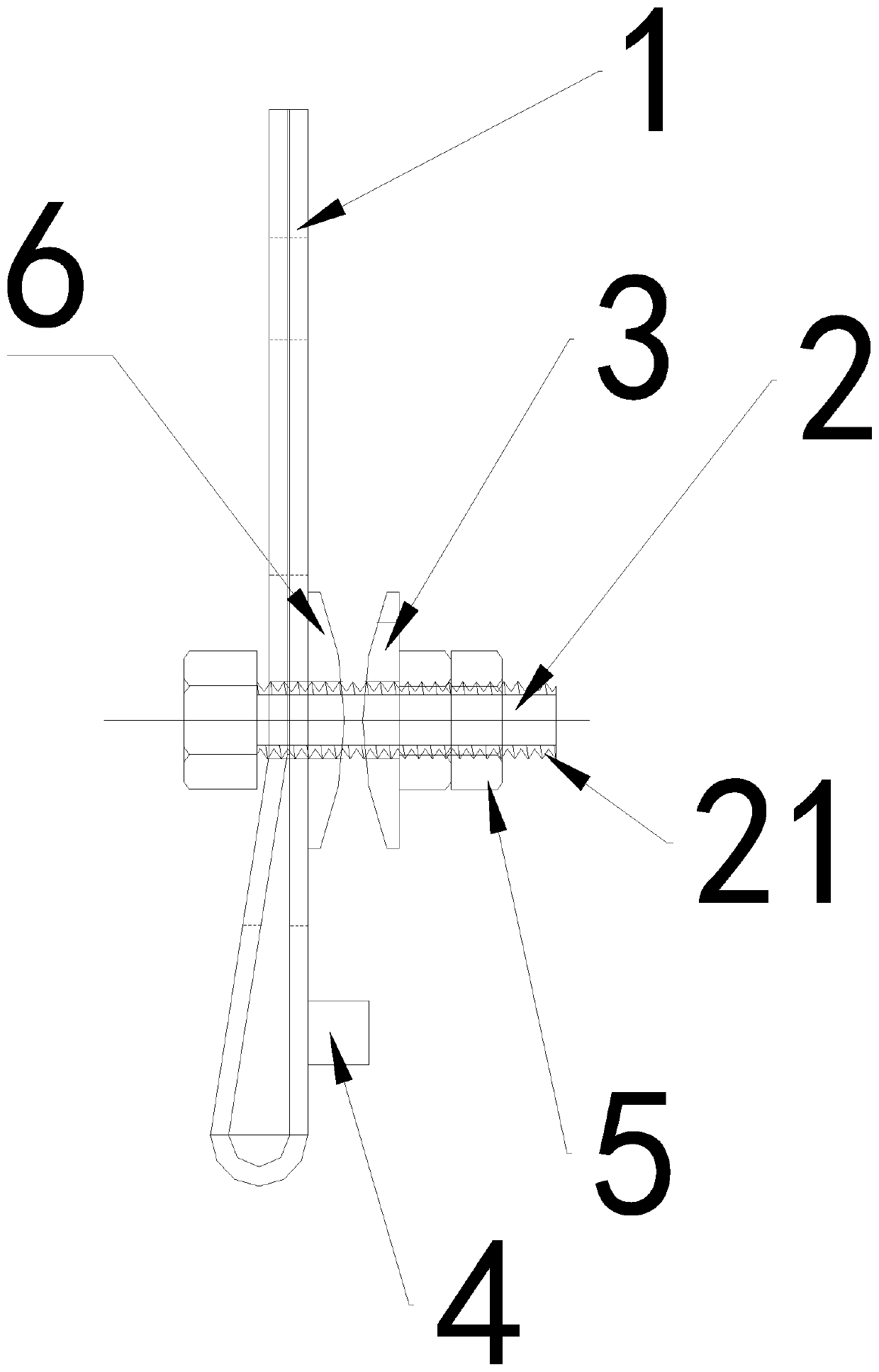
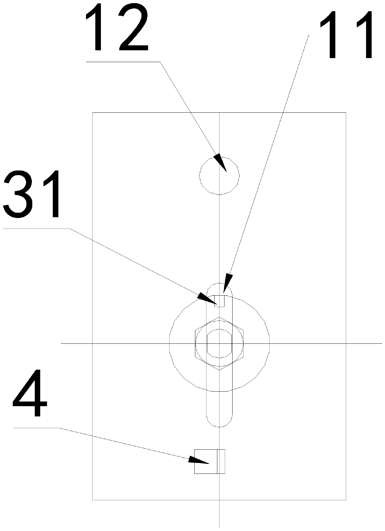
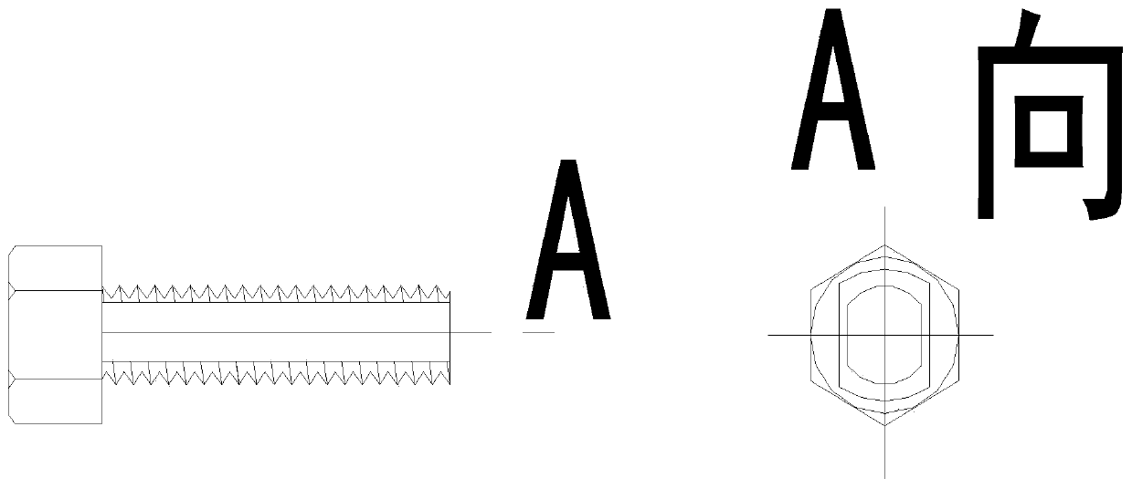
[0027] Such as figure 1 and figure 2 As shown, in combination with the embodiment of the present invention, a self-tightening wire clamp is provided, including a wedge-shaped piece 1, a bolt 2 and a top piece 3; the bolt 2 runs through the wedge-shaped piece 1, and the bolt 2 runs through the top piece Part 3; the top part 3 and the bolt caps of the bolts 2 are respectively located on both sides of the top part 3, and there is an accommodation space between ...


PUM


Abstract

The embodiment of the invention provides a self-tightening type steel wire clamp. The self-tightening type steel wire clamp comprises a wedge-shaped part (1), a bolt (2) and a pressing part (3); the bolt (2) penetrates through the wedge-shaped part (1), and the bolt (2) penetrates through the pressing part (3); and bolt caps of the pressing part (3) and bolt (2) are located on the two sides of thepressing part (3), a containing space is formed between the pressing part (3) and the wedge-shaped part (1), and after an object is contained in the containing space, the pressing part (3) is fixed on the wedge-shaped part (1) through acting force between the pressing part (3) and the wedge-shaped part (1). One person can clamp a steel wire and fix the steel wire clamp on a steel pipe transversely arranged at an opening of a vertical shaft without assistance from other people. Similarly, during repeated measurement, the position movement of the steel wire can be completed through one person,and the steel wire clamp is easy to carry and transfer so that the working intensity of the measuring personnel can be greatly reduced.

Description

technical field [0001] The invention relates to the technical field of engineering measurement, in particular to a wire clip. Background technique [0002] In engineering construction, in order to guide the construction of underground engineering or high-rise building engineering, it is necessary to measure the coordinates and orientation of ground control points to the underground or high-rise, which needs to be realized through plane contact measurement. Especially when carrying out plane connection measurement near the small wellhead shaft, it is generally necessary to hang 2-3 steel wires near the shaft mouth or the transfer port, hang a 5kg weight on one end of the wire near the bottom of the shaft, and place the weight statically In the oil drum with resistance, then observe the steel wire at the same time through the total station on the ground and the total station underground (or high-rise), and realize the plane contact measurement in the form of a contact triangle...

Claims


Application Information

Patent Timeline
IPC IPC(8): F16G11/04F16G11/06
CPCF16G11/044F16G11/06
Inventor 韩兵刘瑞敏韩亦骁
Owner BEIJING URBAN CONSTR EXPLORATION & SURVEYING DESIGN RES INST
Learn More