
A kind of foot bone fixator

A fixer and foot technology, applied in medical science, surgery, etc., can solve the problems of large trauma in bracket installation and complicated fixation surgery, and achieve the effects of reducing difficulty, convenient disassembly later, and saving materials

Active Publication Date: 2017-08-08
NANTONG DUOQIAN NEW MATERIAL SCI & TECH CO LTD
View PDF2 Cites 0 Cited by
  • Summary
  • Abstract
  • Description
  • Claims
  • Application Information

AI Technical Summary

Problems solved by technology

[0007] The technical problem to be solved by the present invention is to overcome the technical problems of large trauma and complicated fixation surgery in the prior art, and provide an orthopedic fixation bracket with less trauma to the installer, which can reduce or even require secondary surgery

Method used


Image

  • A kind of foot bone fixator
  • A kind of foot bone fixator
  • A kind of foot bone fixator

Examples


Embodiment 1

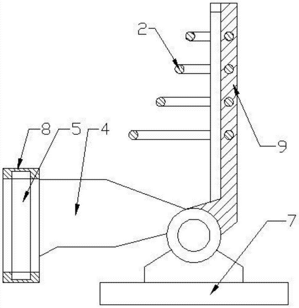
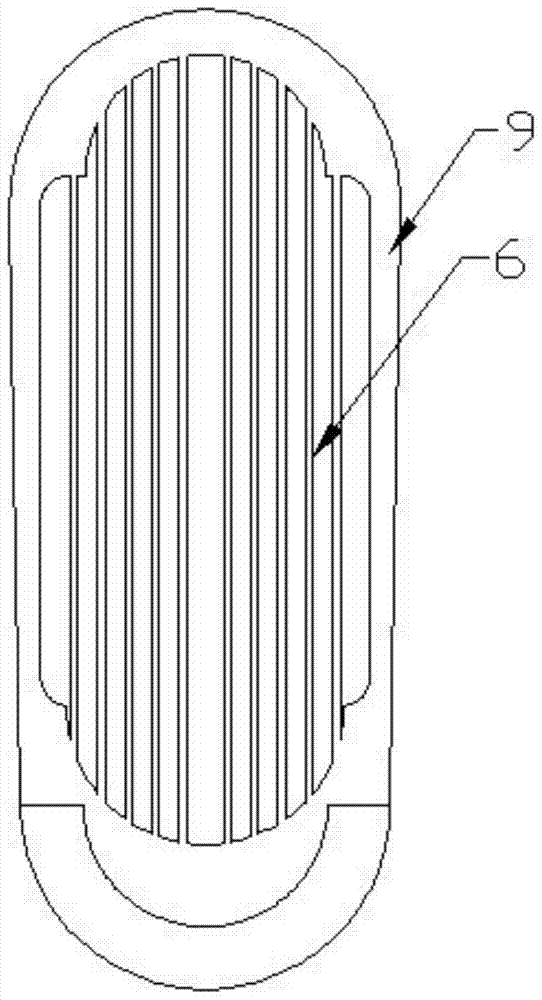
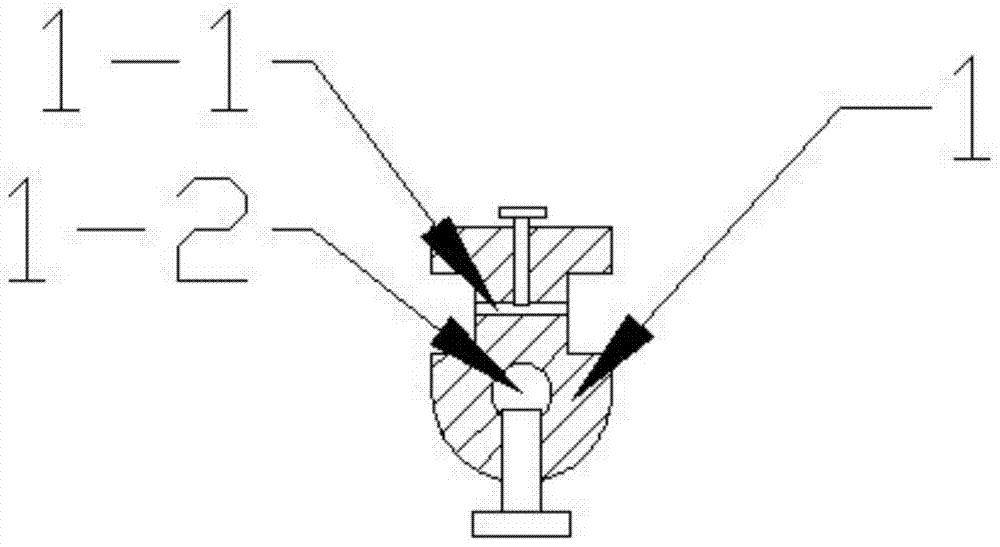
[0042] Such as Figure 1~3 As shown, the present invention is a foot bone fixator, which is mainly used for postoperative bone fixation. The main body of the present invention includes leg fixation ring 8, ankle wrapping plate 4, sole fixer and bone surface fixation assembly, wherein the leg The part fixing ring 8 is annular, and a support bar 5 supported by a spring leaf is also embedded in the inside of the leg fixing ring 8, and the fixed rigidity and stability can be guaranteed by the support bar 5;

[0043] The ankle wrapping plate 4 is two hard plastic plates supported according to the shape of the ankle, and one end of the ankle wrapping plate 4 is fixed on both sides of the leg fixing ring 8, and through the cooperation of the leg fixing ring 8 and the ankle wrapping plate 4, it can Ensure the stability of the fixed position of the human foot;

[0044] The sole immobilizer mainly comprises sole support part, instep fixing assembly and support pad, and sole support par...

Embodiment 2

[0055] At the same time, this product can also be used for the fixation of hand bones, such as Figure 5 , adjust the axis of the sole support plate 9 and the ankle wrapping plate 4 to the same straight line, fix the wall through the leg fixing ring 8, and change the shape of the ankle wrapping plate 4 at the same time to make it correspond to the human wrist. Like the soles of the feet, it is fixed on the soles of the feet support plate 9. In order to ensure the fixing effect, the shape of the fixing rod A can be improved to a wave shape corresponding to the fingers;

[0056] Concrete installation, at first by leg fixing ring 8 and ankle wrapping plate 4, sole support plate 9 is fixed on the palm, and the axis of sole support plate 9 is parallel with the axis of ankle wrapping plate 4 at this moment, and now fixed bar A is pre-fixed On the sole support plate 9, the fixed cable 3 is implanted into the palm and fingers through the operation, and the hand bone is fixed through t...


PUM


Abstract

The invention relates to a foot bone fixator, which comprises an ankle restricting device and a palm fixator, wherein the ankle restricting device comprises a leg fixing ring and an ankle covering plate, the leg fixing ring is fixedly connected with the ankle covering plate, the palm fixator comprises a palm support part, a foot back fixing assembly and a support pad, the palm support part comprises a palm support plate and a fixing part, the fixing part is fixedly connected with the palm support plate, the fixing part is rotationally connected with one side, backing to the leg fixing ring, of the ankle covering plate, the foot back fixing assembly comprises N arc-shaped fixing rods A, the two ends of the fixing rods A are fixedly arranged on the two sides of the palm support plate in the width direction, the middle part of the palm support plate is provided with a hollow hole corresponding to the palm surface, a plurality of fixing rods B are arranged inside the hollow hole in a parallel array way, a bone surface fixing assembly is arranged between the foot back fixing assembly and the palm fixing plate, and comprises fixing blocks arranged on the fixing rods A and the fixing rods B, and fixing cables are arranged among the fixing blocks.

Description

technical field [0001] The invention relates to a foot bone fixator, which relates to an external bone fixator which adopts the cooperation of cables and the foot fixer to fix the bones of the foot. Background technique [0002] In the process of orthopedic treatment such as fractures, various brackets are often used to penetrate the skin surface after surgery to fix the bones to restore them. After recovery, the brackets are removed through trauma surgery. The whole process requires multiple operations. The trauma caused to the human muscle and epidermis is relatively large, and the postoperative recovery period is relatively long. At the same time, the traditional brackets cause relatively large compression and trauma to the bone; [0003] In this regard, on the market now, many orthopedic fixators that can reduce the degree of trauma during surgery and reduce the number of operations to a certain extent, and can accelerate healing at the same time, such as the invention o...

Claims


Application Information

Patent Timeline
Patent Type & Authority Patents(China)
IPC IPC(8): A61B17/60A61L31/02A61L31/06
CPCA61B17/60A61L31/022A61L31/06
Inventor 郇庆霞王敏
Owner NANTONG DUOQIAN NEW MATERIAL SCI & TECH CO LTD
Learn More