
Automatic assembling equipment and method for electric toothbrush handle shell

An automatic assembly and electric toothbrush technology, which is applied to assembly machines, metal processing equipment, positioning devices, etc., can solve problems such as low production efficiency and inaccurate installation accuracy

Pending Publication Date: 2019-11-19
东江精创注塑(深圳)有限公司
View PDF0 Cites 1 Cited by
  • Summary
  • Abstract
  • Description
  • Claims
  • Application Information

AI Technical Summary

Problems solved by technology

[0004] The purpose of the present invention is to overcome the technical problems of low production efficiency and inaccurate installation accuracy in the prior art, to provide an electric toothbrush handle shell automatic assembly device and its method, to realize the rapid and automatic production of the toothbrush handle shell automatic assembly, to achieve Reduce the production cycle, streamline the turnover process, and save labor

Method used


Image

  • Automatic assembling equipment and method for electric toothbrush handle shell
  • Automatic assembling equipment and method for electric toothbrush handle shell
  • Automatic assembling equipment and method for electric toothbrush handle shell

Examples


Embodiment 1

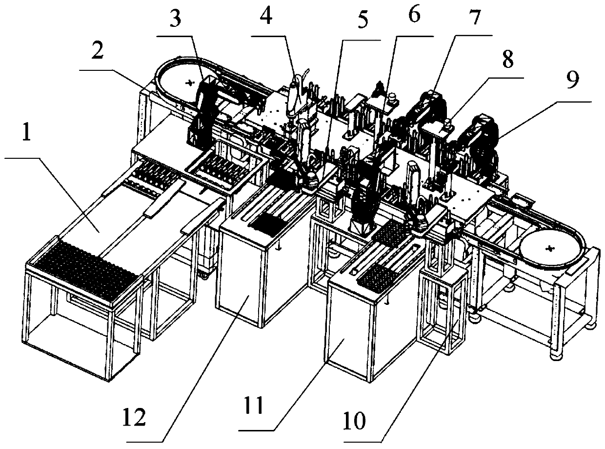
[0057] In the initial state, the device is in standby state. Two kinds of button workpieces are put on the button feeding tray 26, and the top ring workpiece and the bottom ring workpiece are placed on the top ring bottom ring feeding tray 25, and the toothbrush handle shell main body is put into the toothbrush handle feeding tray 24, and the Tray 24 is put into toothbrush handle loading and unloading material work station 1, presses start button to start equipment, and button feed tray 26 and top ring bottom ring feed tray 25 enter into waiting position respectively.

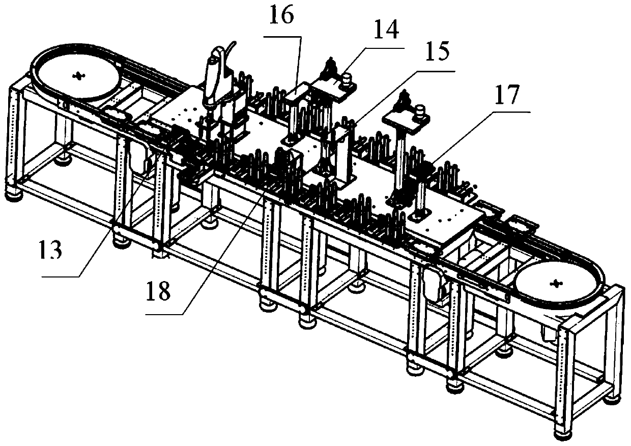
[0058] Centering on the ring-shaped cable 2, along the ring-shaped cable 2, there are toothbrush handle loading and unloading station 1, button installation station, top ring installation station and bottom ring installation station, and toothbrush handle loading and unloading station 1 and button installation station. A second manipulator 4 is arranged between the stations.

[0059] The toothbrush handle load...

Embodiment 2

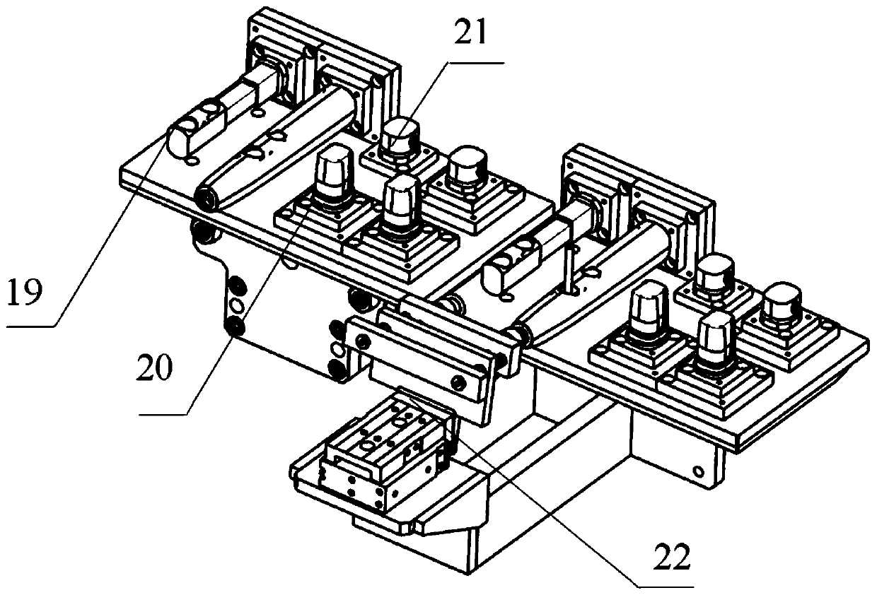
[0073]In the initial state, the device is in standby state. Manually put the toothbrush handle main body shell into the empty toothbrush handle feeding tray 24, place the filled toothbrush handle feeding tray 24 on the feed backguy 27, the toothbrush handle feeding tray 24 enters the waiting position along with the backguy, The first manipulator 3 takes out two unassembled toothbrush handle body shells from the toothbrush handle feeding tray 24 and places them on the button installation positioning fixture 19 on the ring stay wire 2, and places the assembled ones on the bottom ring installation positioning fixture 20 The two toothbrush handle main shells that have been installed are removed and placed in the empty positions of the toothbrush handle feed tray 24. After the toothbrush handle main shells in the toothbrush handle feed tray 24 are fully assembled, the small belt pulls 23 to place the toothbrush handle feed tray 24 is sent to backguy 28, and the toothbrush handle fe...


PUM


Abstract

The invention relates to automatic assembling equipment and method for an electric toothbrush handle shell. The automatic assembling equipment is provided with a toothbrush handle charging and feedingstation, a button mounting station, a top ring mounting station and a bottom ring mounting station at a time with an annular stay wire as a main line; four six-axis manipulators, three four-axis manipulators and three glue dispensers are used for assisting the mounting of a stay wire clamp so as to realize the positioning and moving functions of a toothbrush handle main body; and various stationsand the equipment are connected for communication through a PLC workstation, so that the equipment, workstations and mechanisms are orderly operated in a required manner. Due to the adoption of a servo motor and an air cylinder, the automatic feeding and assembling functions of all accessories of the electric toothbrush handle shell are realized, the traditional mode that manual operation is adopted is changed, and the unmanned and efficient operation of assembly of the electric toothbrush handle shell is realized.

Description

technical field [0001] The invention relates to the technical field of automatic production, in particular to an automatic assembly device and method for an electric toothbrush handle shell. Background technique [0002] Electric toothbrushes are generally used as daily necessities gradually, and the consumption increases sharply. Due to the particularity of the working nature of the electric toothbrush, being in a humid or even water-immersed environment for a long time will lead to water seepage, and even mildew inside the host, causing corrosion of the main board, resulting in electrical failure. Therefore, it is necessary to provide a sealed and waterproof working environment for the main frame of the electric toothbrush to protect structures such as the internal motor of the electric toothbrush and prolong the service life. At present, the rubber material is the most widely used for sealing, and it has the advantages of waterproof, airtight, and not easy to age. [00...

Claims


Application Information

Patent Timeline
IPC IPC(8): B23P21/00B23Q3/08B23Q7/04
CPCB23P21/00B23Q3/08B23Q7/04
Inventor 肖江辉孙雪兵洪志豪
Owner 东江精创注塑(深圳)有限公司
Learn More