Eureka AIR delivers breakthrough ideas for toughest innovation challenges, trusted by R&D personnel around the world.

Direct-current bus voltage control method suitable for low-wind-speed distributed wind power generation

A technology of DC bus voltage and control method, applied in battery circuit devices, current collectors, electric vehicles, etc., can solve the problems of poor control accuracy, insufficient dynamic performance, complex control structure, etc. The control strategy is simple and easy to implement, and the effect of high executable degree

Pending Publication Date: 2019-11-15
NANJING INST OF TECH
View PDF3 Cites 2 Cited by
  • Summary
  • Abstract
  • Description
  • Claims
  • Application Information

AI Technical Summary

Problems solved by technology

Commonly used methods include direct control of the capacitor current based on the instantaneous current of zero parallel capacitors in the DC bus and coordinated power control of the converters on both sides. This method is based on a clear mathematical model and transforms the control mechanism of the converters. , the response speed is fast, but the robustness is poor, and errors are prone to occur, so it is not suitable for low wind speed distributed wind farms with greater turbulence intensity
Another research aimed at the shortcomings of the insufficient dynamic performance of the PI controller used in conventional control, using fuzzy control to achieve dynamic control. This method does not require an accurate mathematical model and has strong robustness, but its control structure is complex and the control accuracy is not good.

Method used


Image

  • Direct-current bus voltage control method suitable for low-wind-speed distributed wind power generation
  • Direct-current bus voltage control method suitable for low-wind-speed distributed wind power generation
  • Direct-current bus voltage control method suitable for low-wind-speed distributed wind power generation

Examples


Embodiment Construction

[0050] The present invention will be further described below with reference to the accompanying drawings and embodiments.

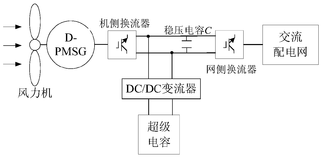
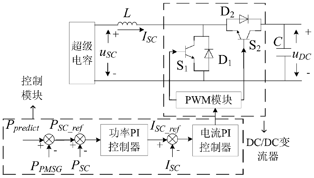
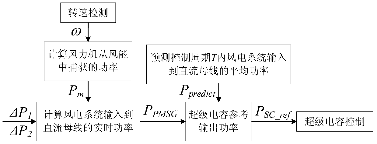
[0051] like figure 1 The low wind speed distributed wind power generation system shown, the low wind speed distributed wind power generation system includes: wind turbine, direct drive permanent magnet synchronous wind generator D-PMSG, machine side converter, voltage stabilizer capacitor C, grid side converter The low wind speed distributed wind power generation system can be directly connected to the AC power distribution network. The low wind speed distributed wind power generation system also includes a super capacitor, which is connected in parallel with a bidirectional DC / DC converter. It is then connected to the DC bus between the machine-side converter and the stabilizing capacitor C, and the DC / DC converter controls the charging and discharging of the super capacitor in any control period T to maintain the DC bus injected into the wind power gene...


PUM


Abstract

The invention discloses a direct-current bus voltage control method suitable for low-wind-speed distributed wind power generation. The low-wind-speed distributed wind power generation system adopted by the control method comprises a wind turbine, a generator, a machine-side converter, a voltage-stabilizing capacitor C, a grid-side converter and a direct-current bus. The low-wind-speed distributedwind power generation system can be directly connected to an alternating-current power distribution network. The low-wind-speed distributed wind power generation system further comprises a super capacitor. The super capacitor is connected in parallel with a bidirectional DC / DC converter and then is connected to a DC bus on the rear side of a machine-side converter. The DC / DC converter controls charging and discharging of the super capacitor in any control period T to maintain power stability of the DC bus injected into the wind power generation system. According to the method, the power stability of the direct current bus can be maintained, so that the delay between the actual value and the reference value of the d-axis current output by the PI regulator in the voltage outer loop control of the grid-side converter is reduced. The voltage stability of the direct-current bus is realized.

Description

technical field [0001] The invention relates to the field of wind power generation, in particular to a DC bus voltage control method suitable for low wind speed distributed wind power generation, which is simple and reliable and can improve the constant voltage control effect of grid-side converters. Background technique [0002] Traditional wind power generation is mostly centralized power generation, and its wind speed characteristics are high amplitude and low turbulence. In order to better develop and utilize wind energy, it is a favorable way to develop distributed wind power near the load center. Low value and high turbulence, it is necessary to find a DC bus voltage control method suitable for distributed wind power with low wind speed. The control of the machine-side and grid-side converters is the core of the permanent magnet direct-drive wind power generation system. The machine-side converter realizes the maximum utilization of wind energy, and the grid-side conve...

Claims


Application Information

Patent Timeline
Patent Type & Authority Applications(China)
IPC IPC(8): H02J3/38H02J7/34
CPCH02J7/345
Inventor 张小莲郝思鹏倪良华韦伟胡佳玮汪麒李恒聪
Owner NANJING INST OF TECH
Why Eureka
Eureka Blog
Learn More