


Quick Research
Generate reliable direction feasibility study reports for your R&D in just a few steps.

Technical Q&A
Discover and master advanced knowledge NOW. Basics, ideas, possibilities, all at once.

Find Solutions
As an expert in R&D theories, this can generate solutions to your technical problems instantly.

Evaluate Feasibility
Analyze your overall solution with one click, know your potential R&D risks in advance.

Monitor Landscape
Get weekly tech updates, stay abreast of the latest tech innovations and key insights.
Display panel control system and display panel control method
A display panel and control system technology, applied in the input/output process of data processing, instruments, fingerprint/palmprint acquisition/arranging, etc., can solve problems such as poor image quality and affecting normal display functions, and improve screen occupation than the effect
- Summary
- Abstract
- Description
- Claims
- Application Information
AI Technical Summary
Problems solved by technology
Method used
Image

Examples
Embodiment 1
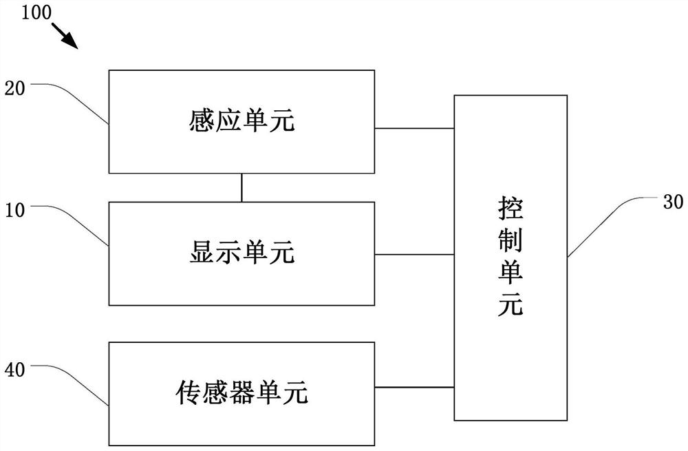
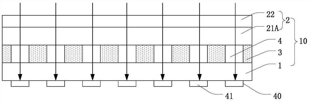
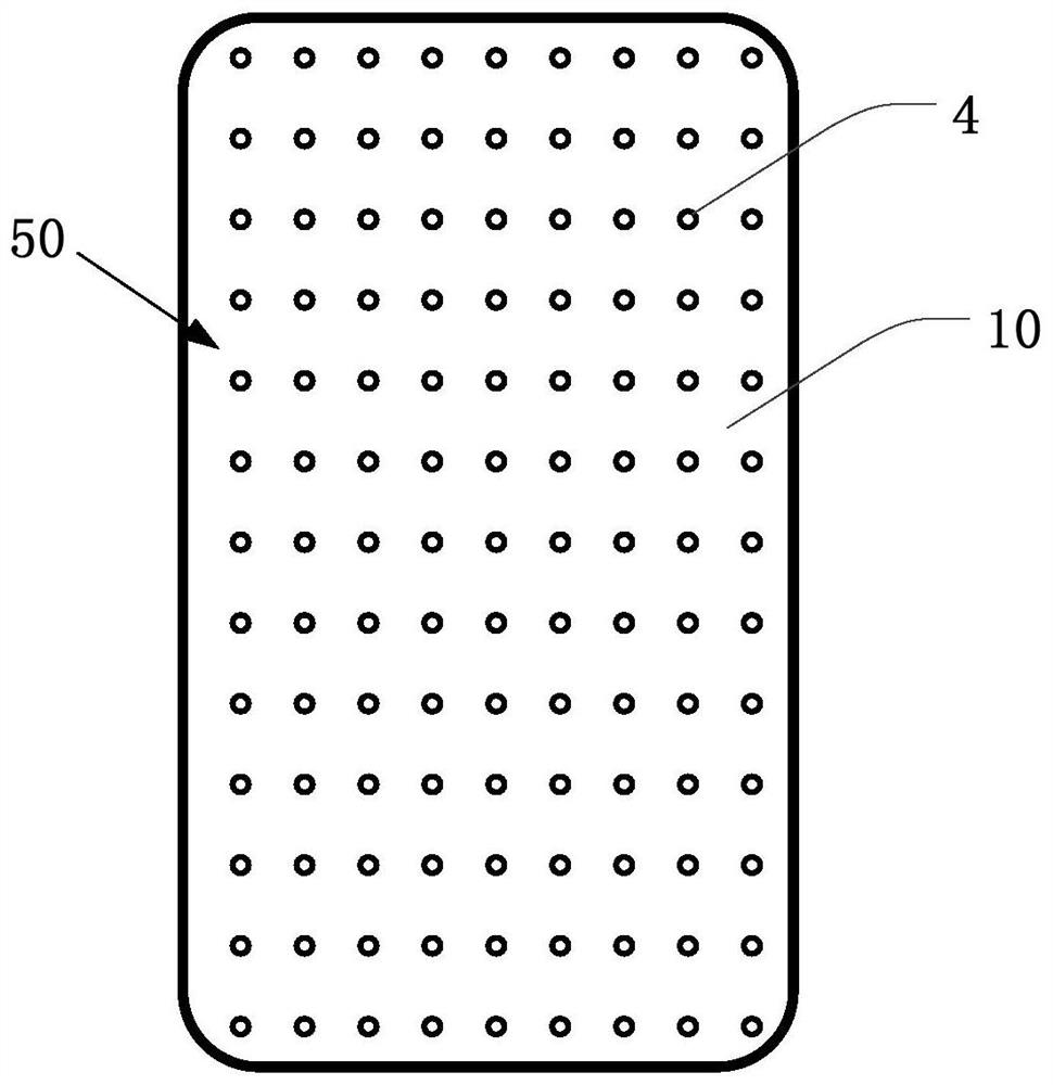
[0038] see figure 1 As shown, a display panel control system 100 is provided in the first embodiment, including a display unit 10 , a sensing unit 20 , a control unit 30 and a sensor unit 40 . Specifically, the display unit 10 is used to display images; the sensing unit 20 is electrically connected to the display unit 10 for sensing the touched area of the display unit 10, and the sensing unit 20 includes a touch layer ; The control unit 30 is electrically connected to the display unit 10 and the sensing unit 20; as figure 2 As shown, when the display unit 10 is touched, it is used to control the formation of a plurality of light-transmitting holes 4 in the touch area for transmitting fingerprint signals; when the display unit 10 is not touched, it is used to control the The display unit 10 performs screen display; the sensor unit 40 is electrically connected to the control unit 30 and is set corresponding to the display unit 10, and is used to receive the fingerprint sign...
Embodiment 2
[0049] see Figure 5 As shown, in the second embodiment, all technical features in the first embodiment are included, and the difference is that the material of the liquid crystal layer 3 in the second embodiment includes thermotropic liquid crystal or lyotropic liquid crystal (ie common liquid crystal) , the liquid crystal molecules include biphenyl liquid crystals, phenylcyclohexane liquid crystals or ester liquid crystals; the first substrate 1 includes an array substrate 11 and a lower polarizer 12, and the lower polarizer 12 is arranged on the array substrate 11B away from One side of the liquid crystal layer 3 ; the second substrate 2 includes a color filter substrate 21B and an upper polarizer 23 , and the upper polarizer 23 is arranged on a side of the color filter substrate 21B away from the liquid crystal layer 3 . Wherein, the combination of the liquid crystal molecules and the upper polarizer 23 and the lower polarizer 12 is to achieve the purpose of controlling li...
PUM
 Abstract
Description
Claims
Application Information
 - R&D Engineer
- R&D Manager
- IP Professional
- Industry Leading Data Capabilities
- Powerful AI technology
- Patent DNA Extraction
Browse by: Latest US Patents, China's latest patents, Technical Efficacy Thesaurus, Application Domain, Technology Topic, Popular Technical Reports.
© 2024 PatSnap. All rights reserved.Legal|Privacy policy|Modern Slavery Act Transparency Statement|Sitemap|About US| Contact US: help@patsnap.com