
A modular structure for convenient laying of floor heating pipelines

A technology of modular structure and floor heating pipes, applied in lighting and heating equipment, hot water central heating systems, heating methods, etc. The effect of fast paving, strengthening bearing strength and improving paving efficiency

Active Publication Date: 2020-11-24
SHANDONG SHANGZHI PIPE IND CO LTD
View PDF9 Cites 0 Cited by
  • Summary
  • Abstract
  • Description
  • Claims
  • Application Information

AI Technical Summary

Problems solved by technology

[0003] When the existing floor heating is paved, the insulation board, reflective film, steel wire mesh, floor heating pipe, cement layer, floor, etc. are generally laid in sequence, that is, layer by layer, especially the insulation board and the floor. The pavement efficiency of the reflective film is low, time-consuming and laborious, which seriously restricts the pavement of the floor heating structure. In order to solve this problem, after special research, it is found that the thermal insulation board and the reflective film can be integrated into one module to facilitate block assembly. At the same time, considering the installation of floor heating pipes and improving the installation efficiency of floor heating pipes, it is necessary to design special pipe clips, further integrate the insulation board, reflective film and pipe clips into an integrated module structure, and consider the impact of the pipe clips on the insulation performance of the insulation board. It is necessary to further optimize the pipe clips, and it is also considered that when the floor heating pipes are installed, the external force impact between the pipe clips and the insulation board is relatively large, and the pipe clips are prone to fall off from the insulation board. In order to further strengthen the floor heating When the pipe is installed, the instantaneous impact resistance between the pipe clip and the insulation board needs to be optimized again

Method used


Image

  • A modular structure for convenient laying of floor heating pipelines
  • A modular structure for convenient laying of floor heating pipelines
  • A modular structure for convenient laying of floor heating pipelines

Examples


Embodiment 1

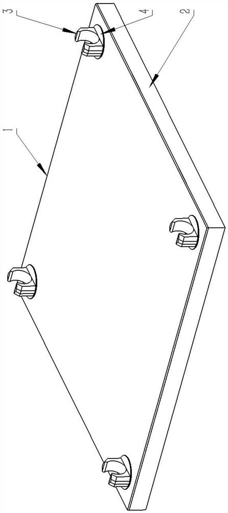
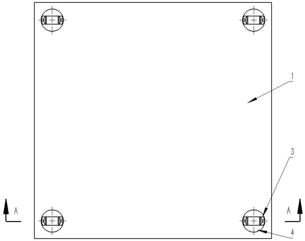
[0048] as attached figure 1 -Attached image 3 As shown, the present invention provides a modular structure for convenient laying of floor heating pipes, comprising a reflective film 1, a thermal insulation board 2 and a pipe clip 3. The thermal insulation board 2 is in the shape of a rectangular plate and the upper end surface is covered with a reflective film 1 to form a thermal insulation module , the four corners of the upper end of the heat preservation module are respectively embedded with pipe clips 3 with the opening facing upward.

[0049] Wherein, the part of the tube clip 3 abutting on the reflective film 1 is fixedly provided with a reinforced bottom plate 4, and the center of the lower end face of the reinforced bottom plate 4 is provided with an embedded block extending vertically downward. The block is a lower insert head 5 whose two lower ends are relatively expanded to form an inverted half-cone block structure and there is a gap between them.

[0050] Where...

Embodiment 2

[0052] On the basis of Example 1, as attached Figure 4 -Attached Figure 5 As shown, four steel mesh opening blocks 7 are evenly distributed at the edge of the upper end face of the reinforcing bottom plate 4, and the distance between the two steel mesh opening blocks 7 that are symmetrical about the center of the reinforcing bottom plate 4 is the same as the opposite two in the steel mesh. The spacing between the steel wires is equal, and the spacing between the adjacent pipe clips 3 of two adjacent modules is equal to an integer multiple of the mesh holes of the steel mesh, so that the steel mesh and each module structure are snapped together, which can improve the insulation board 2 The bearing strength can be improved, and the splicing strength between each module structure can be improved.

Embodiment 3

[0054] On the basis of the second embodiment, as attached Image 6 -Attached Figure 7 As shown, in order to simplify the structure of the embedded block embedded in the thermal insulation module, avoid penetrating the thermal insulation board 2 and enhance the thermal insulation effect, the joint cylinder 6 is cancelled, so that the two lower embedding heads 5 are directly embedded in the thermal insulation board 2 but do not penetrate the thermal insulation board 2. .


PUM


Abstract

The invention discloses a module structure making floor heating pipelines convenient and fast to lay. The module structure comprises a reflection film, a heat preservation plate and pipe clamps, wherein the heat preservation plate is rectangular plate-shaped, and the upper end surface of the heat preservation plate is provided with the reflection film in an adhered mode to form a heat preservationmodule, and the four corners of the upper end of the heat preservation module are embedded with the pipe clamps with upward openings correspondingly; reinforcing bottom plates are fixedly arranged atthe parts, attaching to the reflection film, of the pipe clamps, vertically downwards extended embedding fixing blocks are arranged in the centers of the lower end surfaces of the reinforcing bottomplates, and the embedding fixing blocks are embedded into the heat preservation module. Compared with existing multi-layer sequentially laid floor heating heat preservation structures, the module structure serving as a floor heating heat preservation plate structure capable of being spliced has the advantages that the splicing performance is good, the laying efficiency of the floor heating heat preservation structures can be greatly improved, in view of the connection between the pipe clamps and the heat preservation plate, a structure of simultaneously laying floor heating pipes and the pipeclamps in the prior art is changed, the pipe clamps are integrally clamped on floor heating boards, the modular structure is good, and quick laying of the floor heating pipes is facilitated.

Description

technical field [0001] The invention relates to the technical field of building heating and ventilation construction, in particular to a modular structure for convenient laying of floor heating pipes. Background technique [0002] Floor heating is the abbreviation of radiant floor heating. It uses the entire ground as a radiator, and uniformly heats the entire ground through the heat medium in the radiant layer of the floor, and conducts conduction from bottom to top using the ground's own heat storage and upward heat radiation. heating purpose. Among them, water floor heating refers to a heating method that heats water to a certain temperature and transports it to the water pipe cooling network under the floor, and realizes the purpose of heating through the floor heating. The low-temperature ground heat medium forms a gradually decreasing temperature gradient from the soles of the feet to the head indoors, thus giving people a comfortable feeling of warm feet and cool hea...

Claims


Application Information

Patent Timeline
Patent Type & Authority Patents(China)
IPC IPC(8): F24D3/12F24D19/02
CPCF24D3/127F24D19/02
Inventor 李红国
Owner SHANDONG SHANGZHI PIPE IND CO LTD
Learn More