
Workpiece supporting device for machine tool and mounting method of workpiece supporting device

A technology for supporting devices and workpieces, which is applied in the direction of supporting, positioning devices, metal processing machinery parts, etc., can solve the problems of increased safety hazards, easy deviation of welding quality between partitions and workbenches, and high manual labor intensity, etc., to achieve ingenious design Reasonable, convenient for automatic operation and operation, ensuring the effect of installation firmness

Pending Publication Date: 2019-11-15
新昌卡戎机械科技有限公司
View PDF0 Cites 3 Cited by
  • Summary
  • Abstract
  • Description
  • Claims
  • Application Information

AI Technical Summary

Problems solved by technology

However, in the prior art, the partition and the workbench are generally fixed by welding, and the partition and the workbench are arranged perpendicular to each other. During the welding process, it is necessary to artificially maintain the verticality of the partition. This welding method not only increases safety hazards, Moreover, the manual labor intensity is high, so that the welding quality between the partition and the workbench is also prone to deviation

Method used


Image

  • Workpiece supporting device for machine tool and mounting method of workpiece supporting device
  • Workpiece supporting device for machine tool and mounting method of workpiece supporting device
  • Workpiece supporting device for machine tool and mounting method of workpiece supporting device

Examples


Embodiment Construction

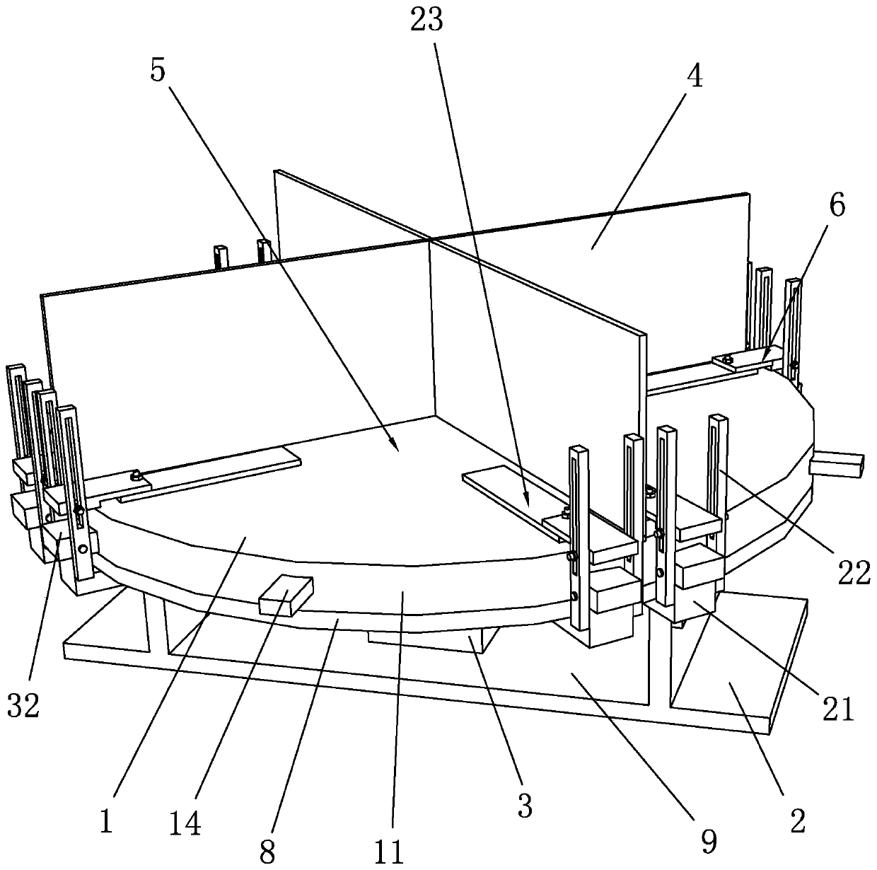
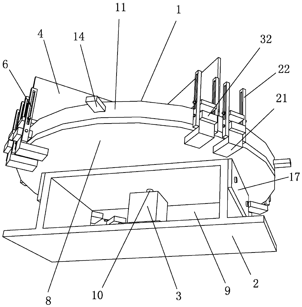
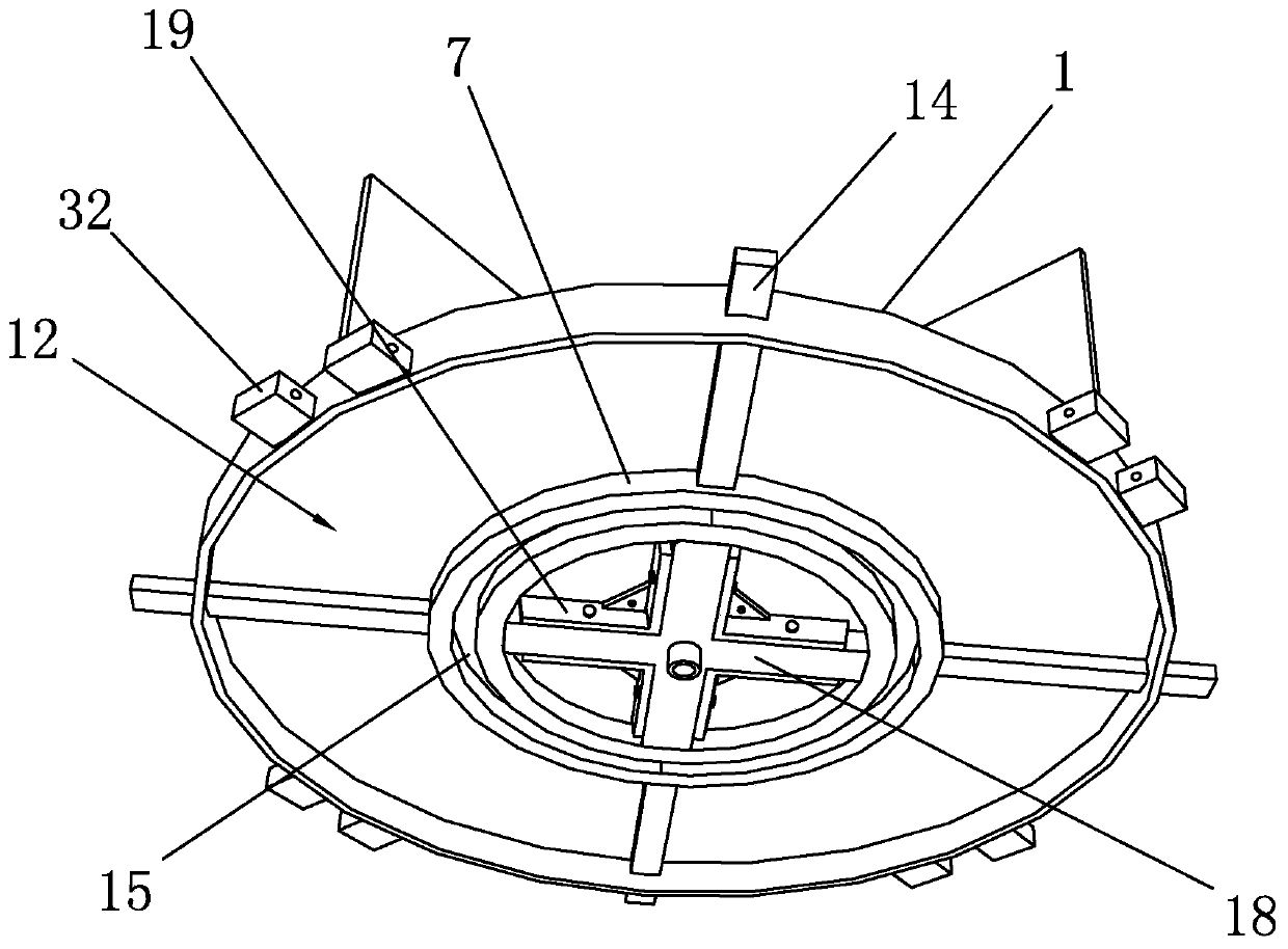
[0046] Such as Figure 1 to Figure 6 As shown, it is a workpiece supporting device for a machine tool of the present invention, including a support platform 1, a fixed seat 2 and a rotating motor 3, and a partition 4 is arranged on the support platform 1, and the partition plate 4 separates the support platform 1 into at least two parts. Each work area 5 is provided with a positioning assembly 6 in each work area 5, the support platform 1 is located above the fixed seat 2, the bottom surface of the support platform 1 is provided with a rotating disk 7, and the top surface of the fixed seat 2 is provided with a The support plate 8 matched with the support platform 1, the support plate 8 is designed to match the support platform 1, which can ensure the support for the bottom of the support platform 1, ensure the stable structure of the support platform 1, and the support plate 8 and the rotating disk 7 are movably clamped The rotary motor 3 is located in the mounting groove 9 of...


PUM


Abstract

The invention discloses a workpiece supporting device for a machine tool. The workpiece supporting device for the machine tool includes a supporting platform, a fixing seat and a rotating motor, a baffle is arranged on the supporting platform, the baffle separates the supporting platform into two or more workspaces, each workspace is internally provided with a positioning assembly, a rotating discis arranged on the bottom surface of the supporting platform, and a support plate matched with the supporting platform is arranged on the top surface of the fixing seat. The invention discloses a mounting method. The mounting method includes the following steps of (1) mounting of the rotating disc and the supporting platform; (2) mounting of the baffle and the supporting platform; (3) mounting ofthe support plate and the fixing seat; (4) mounting of the supporting platform and the support plate; (5) mounting of the positioning assembly and the supporting platform; and (6) mounting of the workpiece supporting device and the machine tool. The workpiece supporting device is ingenious and reasonable in overall structure design, the working efficiency of the machine tool is improved, the friction loss of the supporting platform is reduced, and the energy consumption loss is lowered; and in the mounting process, through auxiliary design of a mounting seat and a positioning sleeve, the mounting difficulty of the workpiece supporting device is reduced, and operational safety during mounting is improved.

Description

technical field [0001] The invention belongs to the technical field of machine tools, and in particular relates to a workpiece support device for machine tools and an installation method thereof. Background technique [0002] A machine tool refers to a machine that manufactures a machine, also known as a machine tool or a tool machine, and is customarily referred to as a machine tool. Generally divided into metal cutting machine tools, forging machine tools and woodworking machine tools. There are many ways to process mechanical parts in modern machinery manufacturing: in addition to cutting, there are also casting, forging, welding, stamping, extrusion, etc. The final machining is done by cutting on the machine tool. Machine tools play an important role in the modernization of the national economy. Ordinary machine tools have a horizontally fixed table adapted to the size of the workpiece to be machined and held on a rigid base. [0003] The existing workbench is equipp...

Claims


Application Information

Patent Timeline
IPC IPC(8): B23Q1/25B23Q7/02B23Q3/06B23K31/02
CPCB23Q1/25B23Q7/02B23Q3/06B23K31/02
Inventor 杨张函
Owner 新昌卡戎机械科技有限公司
Learn More