Novel beam and ram combined structure

A combined structure and crossbeam technology, applied in the field of machine tools, can solve problems such as the influence of machining accuracy, different degrees of wear, and offset of the center of gravity line, and achieve the effects of improving machining accuracy, eliminating bending moments, and uniform force

Pending Publication Date: 2019-11-15
WUYI UNIV
View PDF0 Cites 0 Cited by
  • Summary
  • Abstract
  • Description
  • Claims
  • Application Information

AI Technical Summary

Problems solved by technology

Due to the existence of the cantilever structure, the center of gravity of the main shaft in the vertical direction is offset, which makes the center of gravity of the main shaft and the direction of the processing force required for processing not on the same straight line, resulting in an offset. The processing accuracy is affected, and at the same time, it also makes the beam bear additional bending moment when the product is processed by the machine tool
Moreover, the cantilever structure will cause the upper and lower wire gauges to bear different forces, resulting in different degrees of wear, which will make the cantilever structure more obvious in the later stages of production.

Method used


Image

  • Novel beam and ram combined structure
  • Novel beam and ram combined structure
  • Novel beam and ram combined structure

Examples


Embodiment Construction

[0024] The specific embodiment of the present invention will be further described below in conjunction with accompanying drawing:

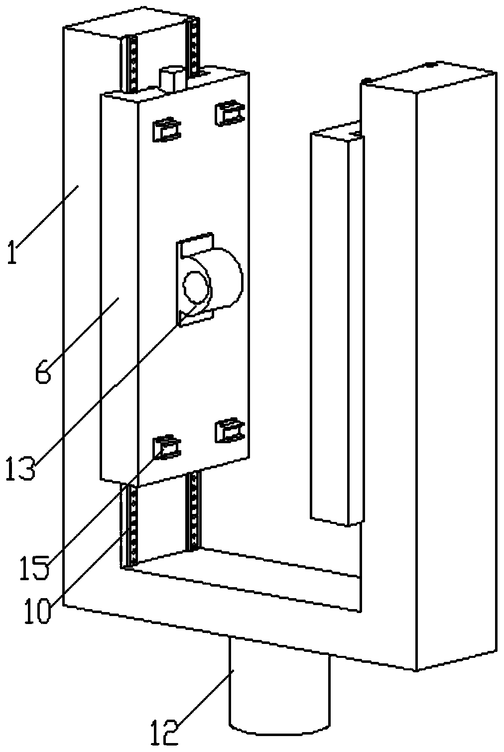
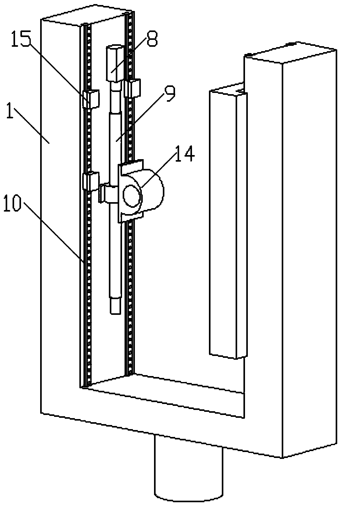
[0025] Such as figure 1 As shown, a novel crossbeam ram combination structure includes a U-shaped ram 1 and a crossbeam 2. The crossbeam 2 is laterally arranged in the groove of the U-shaped ram 1, and the concave of the U-shaped ram 1 The notch is upward, and the U-shaped ram 1 can slide laterally on the beam 2 through two lateral sliding mechanisms symmetrically arranged on both sides of the beam 2 , and along the The beam 2 moves vertically.

[0026] preferred, such as figure 1 and figure 2 As shown, the two sides of the beam 2 are provided with corresponding installation grooves 3 along the length direction, and the two lateral sliding mechanisms are arranged in the corresponding installation grooves 3 . The two described transverse sliding mechanisms have the same structure, and each described transverse sliding mechanism includes a tran...


PUM


Abstract

The invention provides a novel beam and ram combined structure. A U-shaped ram and a beam are included. The beam is transversely arranged in a groove of the U-shaped ram. The U-shaped ram can transversely slide on the beam through two transverse sliding mechanisms symmetrically arranged on the two sides of the beam and vertically move along the beam through two vertical sliding mechanisms symmetrically arranged on the two sides of the beam. A main shaft box is arranged at the center position of the lower end of the U-shaped ram, so that a cantilever structure in the horizontal direction disappears, and influences on product machining precision from the cantilever structure are avoided. Additional bending moment exerted on the beam during product machining due to gravity center deflection of the main shaft box is eliminated. Two lead screws are used for driving a sliding saddle, and it can be guaranteed that the main shaft box part has better advantages in the aspect of rapid braking; meanwhile, stress of the main shaft box is relatively uniform, and the later machining precision is further improved; and two grating rulers are arranged on the side wall of the beam so that movement synchronism of the transverse sliding mechanisms is guaranteed.

Description

technical field [0001] The invention relates to the technical field of machine tools, in particular to a novel beam ram combination structure. Background technique [0002] The three-axis linkage gantry machining center is a multi-purpose machine tool machining center that performs mobile processing on the three axes of X, Y, and Z. Among them, most gantry machining centers use table movement to solve the movement of the X-axis, while the Y-axis and The Z-axis works on the beam and the ram. The beam is fixed on the column, and the ram can move left and right on the beam by relying on the saddle. That is, the saddle moves on the beam with the ram to realize the Y-axis. Movement, for the movement of the Z axis, the up and down movement of the ram relative to the saddle is used to solve the problem. As a result, three-axis linkage is formed, which enables the gantry machining center to realize the machining of complex planes and curved surfaces. As for the word Longmen, it is...

Claims


Application Information

Patent Timeline
Patent Type & Authority Applications(China)
IPC IPC(8): B23Q1/01
CPCB23Q1/012B23Q1/015
Inventor 刘光辉周俊荣胡晨星
Owner WUYI UNIV
Why Eureka
Try Eureka