Dynamic visualization welding joint shearing stress fatigue test device and method

A fatigue test and shear stress technology, applied in the direction of using a stable shear force to test the strength of materials, measuring devices, and using repetitive force/pulse force to test the strength of materials, etc., can solve the problem that the cracking characteristics are difficult to observe and fatigue Cracking, inability to accurately record the cracking process and other problems, to achieve the effect of simple operation, accurate and reliable test results

Active Publication Date: 2019-11-08
HOHAI UNIV
View PDF11 Cites 0 Cited by
  • Summary
  • Abstract
  • Description
  • Claims
  • Application Information

AI Technical Summary

Problems solved by technology

[0004] At present, the fatigue test for the fatigue performance of the steel bridge deck, because the cracking characteristics are difficult to observe, the phenomenon of fatigue cracking may not be found in time, and the cracking process cannot be accurately recorded. Therefore, a test device and test method with full dynamic visualization function are needed

Method used


Image

  • Dynamic visualization welding joint shearing stress fatigue test device and method
  • Dynamic visualization welding joint shearing stress fatigue test device and method
  • Dynamic visualization welding joint shearing stress fatigue test device and method

Examples


Embodiment Construction

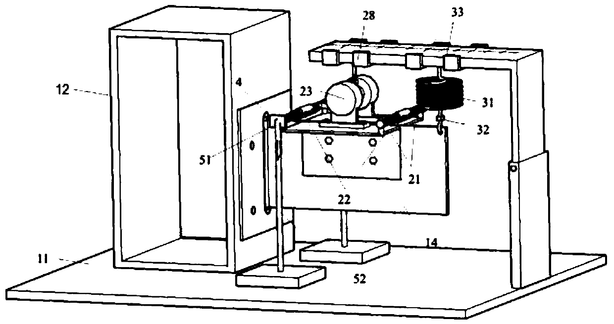
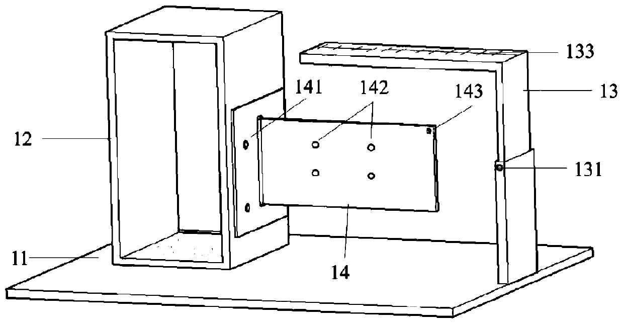
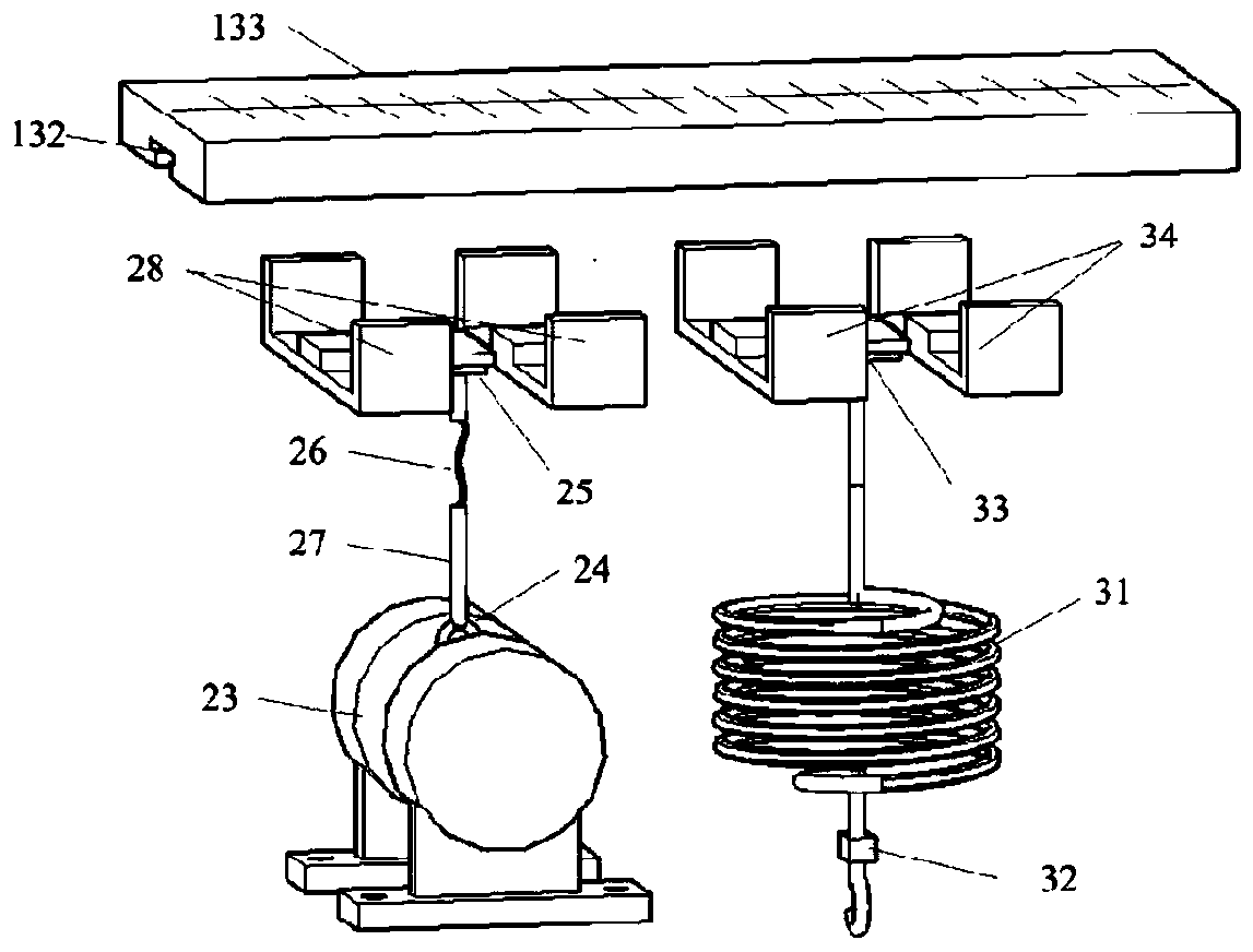
[0031] The present invention will be further described in detail below in conjunction with the accompanying drawings and specific embodiments.

[0032] see Figure 1 to Figure 6 , of which, 1-rack system, 11-bottom plate, 12-rack, 13-mounting frame, 131-fastener, 132-chute, 133-scale line, 141-fixing bolt hole, 142-angle steel bolt hole , 143-spring bolt hole, 2-power system, 21-angle steel, 211-circle, 22-angle steel distance adjustment device, 221-threaded steel pipe, 222-rotary drum, 23-vibration motor, 24-hanging ring, 25-section One slider, 26-steel strand, 27-casing, 28-first slider fixer, 3-stress control system, 31-spring, 32-elasticity monitor, 33-second slider, 34-the first Two slider holders, 4-optical fiber inspection system, 5-visual monitoring system, 51-camera, 52-telescopic frame, 6-PLC integrated system, 61-equipment management module, 62-PLC system, 63-visual management module , 611-elasticity test system, 612-cyclic load test system, 613-fiber optic strain...


PUM


Abstract

The invention provides a dynamic visualization welding joint shearing stress fatigue test device. The dynamic visualization welding joint shearing stress fatigue test device comprises a rack, one endof a test piece with a welding joint is fixed to the rack, and the other end of the test piece is cantilevered; the cantilevered end of the test piece is separately provided with a power system for applying loads in the axial direction of the welding joint and a stress regulation system; the outer side of the test piece is provided with a mounting frame for mounting the power system and the stressregulation system, one ends of the power system and the stress regulation system are connected with the mounting frame separately, and the other ends of the power system and the stress regulation system are connected with the cantilevered end of the test piece separately; an optical fiber detection system is mounted on the test piece, a visualization monitoring system is arranged at the outer side of the welding joint of the test piece, and a stress application system, the stress regulation system, the optical fiber detection system and the visualization monitoring system are connected to a PLC integration system separately. The invention further provides a method utilizing the device. By means of the device, the welding joint can be subjected to a pure shearing stress effect, and the PLCintegration system can dynamically observe the dynamic change process of the shearing stress of the welding joint more visually and conveniently. The method is easy to operate and refined and meets the requirement for the fatigue test of the shearing stress of the welding joint.

Description

technical field [0001] The invention relates to a shear stress fatigue test device and method, in particular to a dynamic and visualized weld shear stress fatigue test device and method. Background technique [0002] The structure of the steel bridge deck is complex, and welds are often used to connect the various structures. However, due to welding defects and large welding residual stresses in the welds, fatigue damage and fatigue cracks are prone to occur under repeated loads. Common cracks in the steel bridge deck include welds between the top plate and U-ribs, welds between diaphragms and U-ribs, and butt welds between U-ribs. The stress characteristics of parts prone to fatigue cracks are different. For example, the U-rib butt weld mainly bears tensile stress; stress is more pronounced. [0003] At present, the strength or life research of the above structural details usually uses S-N curves for research, but the fatigue strength curves of normal stress and shear str...

Claims


Application Information

Patent Timeline
Patent Type & Authority Applications(China)
IPC IPC(8): G01N3/24G01N3/38G01N3/06
CPCG01N3/068G01N3/24G01N3/38G01N2203/0005G01N2203/0025G01N2203/005G01N2203/0066G01N2203/0073G01N2203/0641G01N2203/0647
Inventor 姚悦吉伯海傅中秋
Owner HOHAI UNIV
Why Eureka
Try Eureka