Combining force control search assembly method

An assembly method and flexible assembly technology, applied in the direction of assembly machines, metal processing equipment, manufacturing tools, etc., can solve the problems of poor machining accuracy, affecting the production process, not satisfying automation, etc., to improve dynamic characteristics, improve assembly success rate, Improve the effect of dynamic response characteristics

Active Publication Date: 2021-09-03
珞石(北京)科技有限公司
View PDF0 Cites 1 Cited by
  • Summary
  • Abstract
  • Description
  • Claims
  • Application Information

AI Technical Summary

Problems solved by technology

[0003] Due to the large amount of uncertainty in the assembly site, traditional robots cannot meet the assembly requirements. For example, stamping workpieces may have problems such as poor processing accuracy and poor consistency. Then there will be a situation where the position error between the two workpieces to be assembled is greater than the fit clearance. Due to the high joint stiffness of traditional industrial robots, the trajectory of each assembly is unchanged, and it is very likely that there will be problems such as assembly failure, resulting in damage to the workpiece and other consequences.
[0004] Now a solution is to use vision positioning technology to guide the robot to assemble by vision. This method can reduce the position error between workpieces to a certain extent, but there are still large gaps in the occasions where assembly accuracy is high. Probability of assembly failure, affecting the production process
At present, there are still many occasions where manual assembly is used. Workers perceive the force of the workpiece during assembly and adjust the assembly position at all times to achieve the purpose of assembly. However, the efficiency is low when dealing with the assembly of large-quality workpieces, and it does not meet the requirements of automation.

Method used


Image

  • Combining force control search assembly method
  • Combining force control search assembly method
  • Combining force control search assembly method

Examples


Embodiment Construction

[0058] Embodiments of the present invention are described in detail below, examples of which are shown in the drawings, wherein the same or similar reference numerals designate the same or similar elements or elements having the same or similar functions throughout. The embodiments described below by referring to the figures are exemplary and are intended to explain the present invention and should not be construed as limiting the present invention.

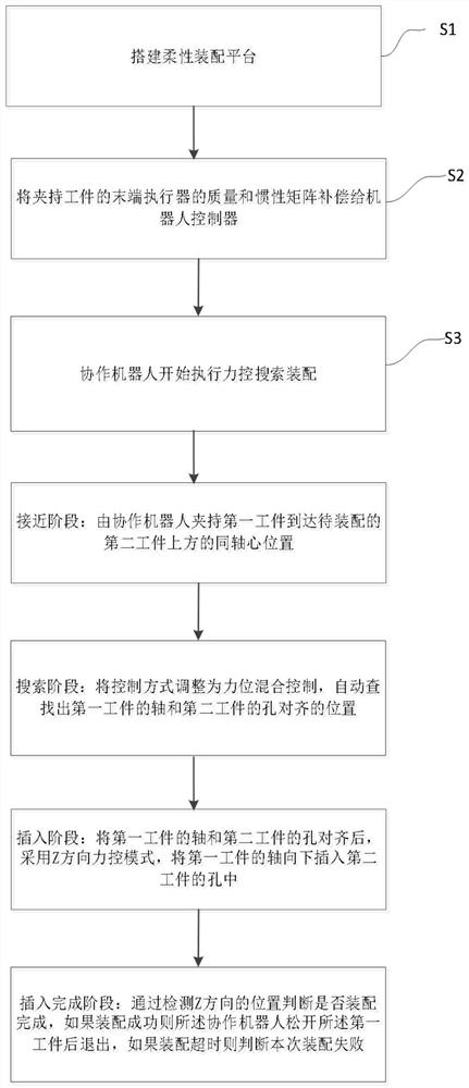
[0059] Such as figure 1 As shown, the search and assembly method combined with force control in the embodiment of the present invention includes the following steps:

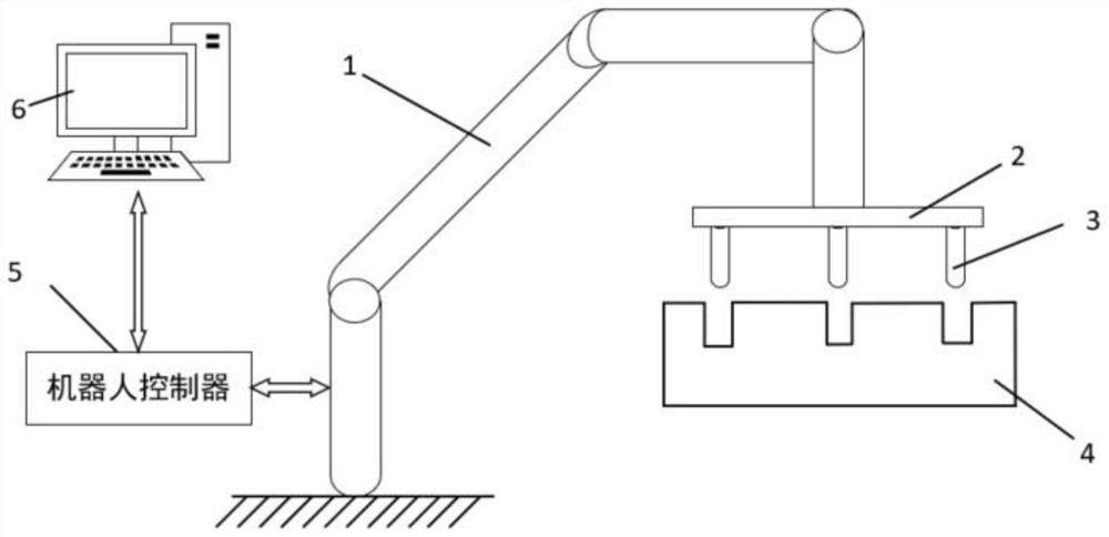
[0060] Step S1, build a flexible assembly platform based on the collaborative robot, combined with force control and search algorithms. Such as figure 2 As shown, the flexible assembly platform includes: a collaborative robot body 1, a collaborative robot controller 5, a host computer 6, an end effector 2, an assembly workpiece axis 3, and an assembly workpiece ...


PUM


Abstract

The present invention proposes a search and assembly method combined with force control, which includes the following steps: building a flexible assembly platform; compensating the mass and inertia matrix of the end effector that clamps the workpiece to the robot controller; the collaborative robot starts to perform force control search and assembly , including the following stages: the first workpiece is clamped by the collaborative robot to the coaxial center position above the second workpiece to be assembled; the control method is adjusted to force-position hybrid control, and the axis of the first workpiece and the axis of the second workpiece are automatically found Hole alignment position; after aligning the axis of the first workpiece with the hole of the second workpiece, use the Z-direction force control mode to insert the axis of the first workpiece downward into the hole of the second workpiece; judge by detecting the position in the Z direction Whether the assembly is complete, if the assembly is successful, the collaborative robot will release the first workpiece and exit. The invention embodies flexibility in the assembly process, not only improves the assembly success rate, but also does not damage the robot or the tool workpiece.

Description

technical field [0001] The invention relates to the technical field of industrial robots, in particular to a search and assembly method combined with force control. Background technique [0002] In the field of automobile manufacturing and assembly, a large number of parts need to be assembled after processing. In order to meet the needs of automation, industrial robots have been widely used in automobile assembly sites. Compared with manual assembly, assembly using traditional industrial robots has the characteristics of high repeat positioning accuracy, high efficiency, large range of motion, and high load. [0003] Due to the large amount of uncertainty in the assembly site, traditional robots cannot meet the assembly requirements. For example, stamping workpieces may have problems such as poor processing accuracy and poor consistency. Then there will be a situation where the position error between the two workpieces to be assembled is greater than the fit clearance. Due...

Claims


Application Information

Patent Timeline
Patent Type & Authority Patents(China)
IPC IPC(8): B23P21/00
CPCB23P21/00
Inventor 刘凯庹华曹华王皓韩建欢于文进
Owner 珞石(北京)科技有限公司
Why Eureka
Try Eureka