
Hybrid maglev gravity compensation apparatus

A gravity compensation and magnetic levitation technology, which is applied in the field of gravity compensation devices, can solve problems such as high motor heat generation, affecting the thermal performance of the wafer holder, and air flow disturbance

Active Publication Date: 2011-09-28
SHANGHAI MICRO ELECTRONICS EQUIP (GRP) CO LTD +1
View PDF6 Cites 31 Cited by
  • Summary
  • Abstract
  • Description
  • Claims
  • Application Information

AI Technical Summary

Problems solved by technology

The former's air-floating structure is difficult to design and manufacture and may cause certain airflow disturbances, while the latter's motor will generate too much heat and will inevitably affect the thermal performance of the wafer holder

Method used


Image

  • Hybrid maglev gravity compensation apparatus
  • Hybrid maglev gravity compensation apparatus
  • Hybrid maglev gravity compensation apparatus

Examples


Embodiment Construction

[0024] In the following, preferred embodiments according to the present invention will be described in detail with reference to the accompanying drawings.

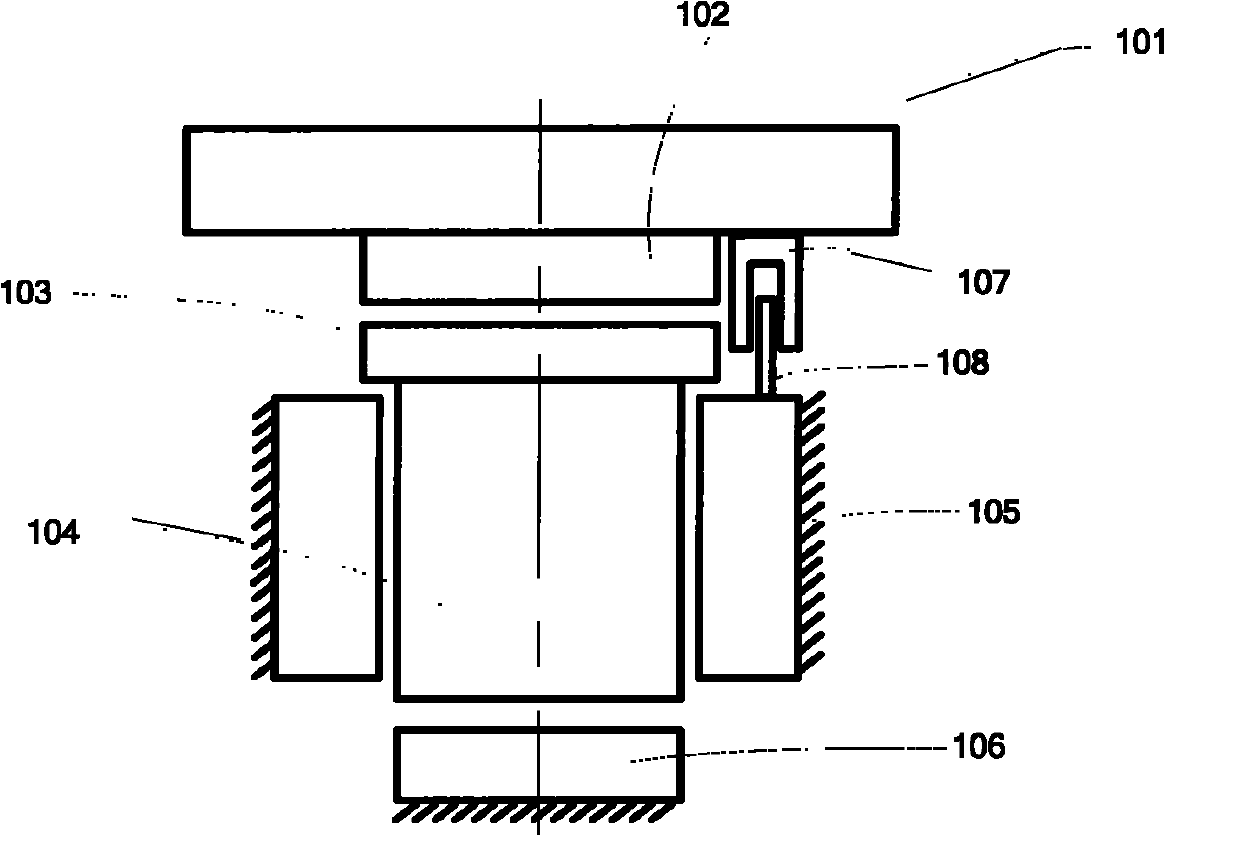
[0025] Such as figure 1 As shown, the connecting part 102 is placed under the micro-moving wafer stage part 101, and the connecting part 102 and the top part 103 below it together form a horizontal (X / Y direction) decoupling part; the middle moving part 104 and the external fixed part 105 The vertical guide part; the middle moving part 104 and the bottom fixed part 106 form a static vertical gravity compensation part. The decoupling part and the guide part together form a moving part, and the outer fixing part 105 and the bottom fixing part 106 are stationary parts. When it is necessary to measure the vertical displacement of the gravity compensation device, a differential sensor can be used—the stator part 108 of the sensor is installed on the bottom fixed part 106 or the external fixed part 105, and the mover part 107 o...


PUM


Abstract

The invention discloses a hybrid maglev gravity compensation apparatus comprising a static gravity compensation module. The static gravity compensation module comprises: an intermediate moving component, an exterior fixed component arranged around the intermediate moving component, and a bottom fixed component arranged below the intermediate moving component. The intermediate moving component is in a radially suspended state with the magnetic forces between the exterior fixed component and the intermediate moving component, such that a vertical guiding to the intermediate moving component is carried out. Static gravity compensating between the exterior fixed component and the intermediate moving component can be carried out with adjustable magnetic forces. According to the invention, non-contact displacement between relatively moving objects can be achieved with maglev forces. Meanwhile, gravity compensation, horizontal and vertical decoupling of a wafer supporting stage can be achieved.

Description

technical field [0001] The invention relates to a hybrid maglev gravity compensation device. Background technique [0002] With the continuous improvement of the integration level of large-scale integrated circuit devices and the continuous enhancement of lithography resolution, the requirements for the characteristic line width index of lithography machines are also constantly increasing. At present, the lithography machine has developed into a combination of the internal world and the external world, among which the three independent worlds of the workpiece table, the mask table and the lighting system are respectively vibration-reduced and vibration-isolated. [0003] Taking the micro-movement module as an example, it is very important to prevent the wafer table from being disturbed by the vibration of the workpiece table system and the basic frame during the exposure process. It is necessary to adopt an effective solution to reduce and isolate the wafer table. The gravi...

Claims


Application Information

Patent Timeline
Patent Type & Authority Applications(China)
IPC IPC(8): G03F7/20
Inventor 方洁吴立伟齐宁宁齐芊枫
Owner SHANGHAI MICRO ELECTRONICS EQUIP (GRP) CO LTD
Learn More