A long-distance, precise and fast pick-and-place chip device

A long-distance, chip technology, applied in the direction of transportation and packaging, electrical components, conveyor objects, etc., can solve the problem that the wafer pick-and-place structure cannot meet the long-distance transmission industrial production requirements at the same time, and cannot make the center of the loading nozzle visually positioned Center, unable to meet the needs of huge transfer of film loading capacity, etc., to achieve the effect of reducing motor load and moment of inertia, satisfying long-distance transmission, improving film loading efficiency and film loading yield

Active Publication Date: 2022-01-04
SUZHOU ACCURACY ASSEMBLY AUTOMATION CO LTD
View PDF15 Cites 0 Cited by
  • Summary
  • Abstract
  • Description
  • Claims
  • Application Information

AI Technical Summary

Problems solved by technology

However, there are two problems in the actual implementation process: 1) In the process of taking the film, the position of the film loading nozzle is not corrected, and it is impossible to make the center of the film loading nozzle, the center of the thimble, and the visual positioning center three points and one line, so it cannot Picking up the chip at the center of the chip may even lead to the failure of picking up the chip; 2) During the loading process, when multiple groups of wafer pick-and-place seats rotate at 360 degrees at high speed, there is no visual positioning device placed on the wafer position, and the x, y Moving multiple groups of wafer pick-and-place seats in the same direction makes the pick-and-place position of the chip inaccurate, and the chip cannot be accurately placed on the loading station on the carrier substrate, which greatly reduces the yield of the wafer loading; especially in micro LED and fan out and other advanced packaging fields, it is necessary to remove the chip from the wafer and place it on another panel or wafer as large as possible with high precision and high speed to obtain good economic benefits
This long-distance requirement between the pick-up and loading stations often conflicts with the high-speed and high-precision requirements of the loading process, resulting in the existing wafer pick-and-place structure being unable to meet the requirements of long-distance transmission and loading accuracy of less than ±10 μm at the same time. Industrial production requirements, not to mention that it cannot meet the huge transfer requirements with a loading capacity of not less than 20k pieces / h, and urgently needs to be improved

Method used


Image

  • A long-distance, precise and fast pick-and-place chip device
  • A long-distance, precise and fast pick-and-place chip device
  • A long-distance, precise and fast pick-and-place chip device

Examples


Embodiment Construction

[0050] The technical solution of the present invention will be clearly and completely described below.

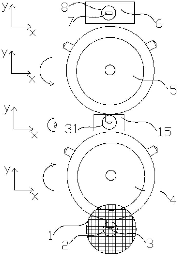
[0051] It should be noted that "horizontal", "vertical", "front", "rear", "left", "right", "upper" and "lower" refer to the attached Image 6 The direction in is also the direction of the use position of the long-distance, precise and quick pick-and-place chip device of the present invention. "X direction" and "Y direction" are relative to figure 1 with Figure 4 In terms of the coordinate system in , and figure 1 with Image 6 The coordinate system in is the result of the two representations in the same coordinate system.

[0052] Such as figure 1 As shown, a long-distance, precise and fast chip pick-up device includes a wafer stage and a wafer stage 6, the wafer stage is used to place a wafer 1, and the wafer stage 6 is used to place a substrate 7;

[0053] A first turret 4 and a second turret 5 are arranged between the wafer stage and the wafer stage 6, and at leas...


PUM


Abstract

The present invention provides a long-distance, accurate and quick chip picking and loading device, which includes a wafer stage and a chip carrier, the wafer stage is used to place wafers, and the chip carrier is used to place substrates; the wafer stage A first turret and a second turret are arranged between the wafer table and at least three suction nozzles are arranged at equal intervals in the circumferential direction of the first turret and the second turret for taking out and placing the wafer on the wafer. chip; a correction table is set between the first turret and the second turret, for transferring the chip between the first turret and the second turret; the first turret and the second turret Set the rotary drive; set the vertical motion drive. The rotary tower of the present invention can realize 360° step-by-step rotation in the horizontal direction, and simultaneously completes the film taking and film loading actions, which reduces the rotation angle and greatly improves the film loading efficiency. Great improvement.

Description

technical field [0001] The invention relates to the field of packaging of semiconductor components, in particular to a long-distance, precise and fast pick-and-place chip device. Background technique [0002] In the field of microelectronics technology, we often use packaged semiconductor components or chips. During the packaging process, the semiconductor chip on the wafer needs to be removed and placed on the carrier substrate. Specifically, it is first necessary to use The glue dispensing mechanism dispenses glue on the loading station on the loading substrate, and then the semiconductor chip is taken out from the wafer by the loading nozzle of the loading mechanism, and then transferred to the loading station where the glue has been dispensed; Among them, in the process of picking up the wafer, an thimble is set under the blue film of the wafer, and a visual positioning device is set on the blue film of the wafer: first, by judging the position of the chip on the wafer, ...

Claims


Application Information

Patent Timeline
Patent Type & Authority Patents(China)
IPC IPC(8): H01L21/677H01L21/683
CPCH01L21/67703H01L21/6838H01L21/677H01L21/683
Inventor 王敕
Owner SUZHOU ACCURACY ASSEMBLY AUTOMATION CO LTD
Why Eureka
Try Eureka