
Improved electronic transformer current collection method

A technology of electronic transformer and acquisition method, which is applied to instruments, simulators, and measurement using digital measurement technology, etc., can solve the risk of accuracy and reliability, abnormal integration link, and the accuracy of integration link cannot be well guaranteed. and other problems, to improve the sampling accuracy and reliability, and solve the effect of anti-interference.

Pending Publication Date: 2019-11-12
GUIZHOU POWER GRID CO LTD
View PDF5 Cites 2 Cited by
  • Summary
  • Abstract
  • Description
  • Claims
  • Application Information

AI Technical Summary

Problems solved by technology

Both of these two solutions have certain technical shortcomings. Because the accuracy and reliability of hardware integration are limited by the electrical parameters of electronic components, there are risks in their accuracy and reliability; the software integration implemented by the merging unit is subject to the collector The sampling bandwidth and transmission rate are limited, and due to the existence of spectral aliasing, low-frequency noise, voltage drift and other phenomena, as well as the limitation of the electrical parameters of the electronic device itself, the accuracy of the integration link cannot be well guaranteed, and even the distortion of high-frequency signals It will lead to an abnormality in the integration link
Therefore, there are certain risks in the accuracy and reliability of the existing acquisition methods, and there is still a large room for improvement in the electronic transformer current acquisition method

Method used


Image

  • Improved electronic transformer current collection method
  • Improved electronic transformer current collection method
  • Improved electronic transformer current collection method

Examples


Embodiment

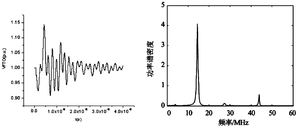
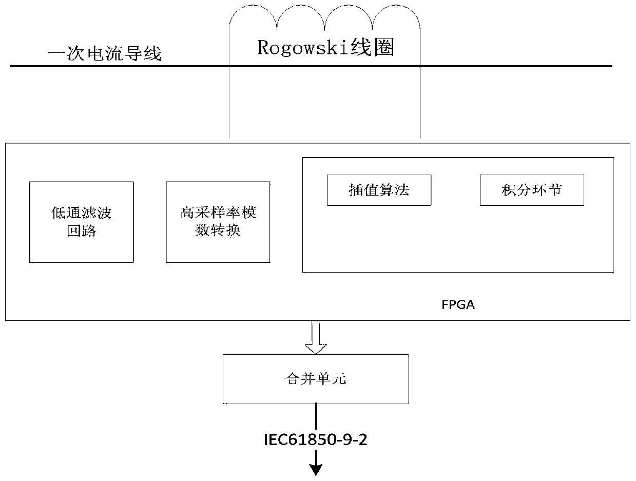
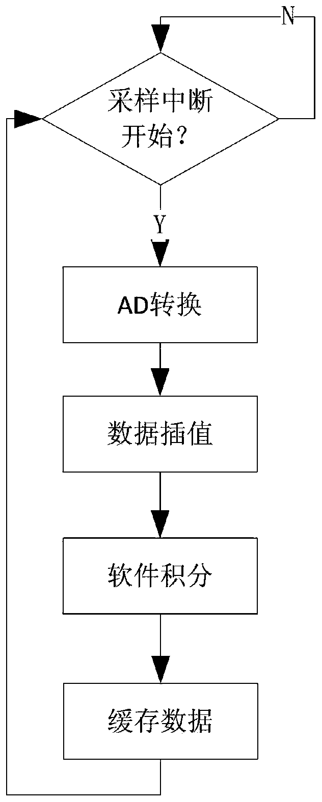
[0034] Example: such as Figure 1-Figure 6 As shown, an improved electronic transformer current acquisition method, the method includes the following steps:

[0035] (1) Sampling is performed by a digital-to-analog conversion chip, and the digital-to-analog conversion chip adopts a 16-bit digital-to-analog conversion chip;

[0036] (2) Use the data interpolation algorithm to perform data interpolation calculation on the sampled data to obtain the power system power waveform, and judge whether the sampled value is valid according to the segmental continuous conduction of the power system power waveform, if invalid, use the Newton interpolation method to update the invalid sampled value ;

[0037] In step (1), the digital-to-analog conversion chip adopts AD7606, which has a built-in second-order anti-aliasing analog filter, and the sampling frequency is 40kSPS.

[0038] The high-precision acquisition of the electronic current transformer acquisition unit of the present inventi...


PUM


Abstract

The invention discloses an improved electronic transformer current collection method. The method comprises the following steps of (1) sampling through a digital-to-analog conversion chip, wherein thedigital-to-analog conversion chip adopts a 16-bit digital-to-analog conversion chip; and (2) performing data interpolation operation on sampled data by using a data interpolation algorithm in order toobtain an electric quantity waveform of an electric power system, judging whether a sampling value is valid or not according to the piecewise continuous derivability of the electric quantity waveformof the electric power system, and updating the invalid sampling value by adopting a Newton interpolation method if the sampling value is invalid. According to the method, the sampling precision and the Nyquist cut-off frequency of a collection unit are improved; and the Newton interpolation method is used for carrying out data processing on the sampled signal to filter out the low-frequency noisecaused by spectrum aliasing and the burrs of the system, so that the problems of anti-interference performance, low precision of an integral link and distortion of an electronic transformer collectorare effectively solved, the sampling precision and reliability of the electronic transformer collector are improved, and a guarantee is provided for the normal operation of a rear-end merging unit and a protection device.

Description

technical field [0001] The invention belongs to the technical field of electric power system automation, and in particular relates to an improved electronic transformer current collection method. Background technique [0002] The Rogowski coil is the most commonly used sensing unit in the light-transmitting current transformer. At present, most of the electronic transformers used in China are based on this. It is an air-core inductance coil formed by uniformly winding wires on a non-magnetic skeleton with a circular equal cross-section. Its output voltage is proportional to the differential signal of the primary current with respect to time. Therefore, the integral link is a necessary link based on the current acquisition of the Rogowski coil current transformer. The accuracy of the integral determines the accuracy of the final signal restoration. The quality of the integral link will directly affect the The transient steady-state performance of the electronic transformer, ...

Claims


Application Information

Patent Timeline
IPC IPC(8): G01R19/25G05B19/042
CPCG01R19/25G05B19/0428G05B2219/2612
Inventor 孟令雯王宇辛明勇高吉普徐长宝林呈辉吕黔苏汪明媚顾威古庭赟
Owner GUIZHOU POWER GRID CO LTD
Learn More