
Novel plug-in steel cylinder wind power base

A wind power foundation and steel cylinder technology, applied in infrastructure engineering, construction, etc., can solve the problems of long construction period, high cost, and high project cost, and achieve the effects of easy construction, good wave resistance, and high safety

Pending Publication Date: 2019-11-12
CCCC FHDI ENG
View PDF0 Cites 4 Cited by
  • Summary
  • Abstract
  • Description
  • Claims
  • Application Information

AI Technical Summary

Problems solved by technology

[0005] The purpose of the present invention is to provide a new type of plug-in steel cylinder wind power foundation, and propose a new type of gravity foundation combined with a negative pressure cylinder foundation jacket with a hollow structure on the upper part, and a vibration sinking large cylinder jacket foundation scheme, which is innovative The foundation bearing mode of the foundation-soil coordination maximizes the bearing capacity of the soft soil layer above the foundation, avoids the need for rock-socketing in traditional pile foundations to meet the bearing capacity requirements, and solves the problem of the high cost of the traditional offshore wind power foundation structure. Pile or multi-pile foundations and jacket foundations require rock-socketed construction at higher rock surfaces, resulting in long construction periods and high project costs

Method used


Image

  • Novel plug-in steel cylinder wind power base
  • Novel plug-in steel cylinder wind power base
  • Novel plug-in steel cylinder wind power base

Examples


Embodiment 1

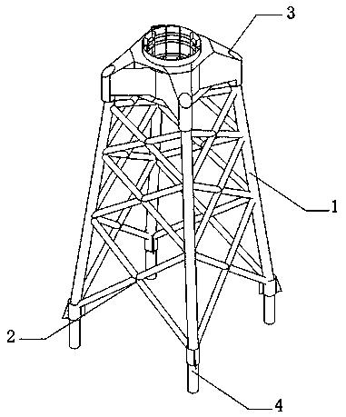
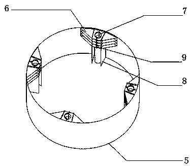
[0039] refer to figure 1 , figure 2 and Figure 4, the steel cylinder 5 is welded with reserved steel sleeves 7 at the four positions corresponding to the upper jacket structure leg piles 4, if the upper jacket is a three-pipe type, the reserved steel sleeves 7 and its adjacent parts will be correspondingly reduced , the reserved steel sleeve 7 and the upper jacket 1 are arranged at equal intervals along the circumference of the steel cylinder 5, the diameter of the reserved steel sleeve 7 is 2.0m-3.0m, and the space between the leg pile 4 and the reserved steel sleeve 7 It is connected by grouting, and the inclined plate at the end of the steel sleeve 7 is reserved for sealing to avoid clearing the hole. The length is 10m-45m, depending on the soft soil conditions. The reserved steel sleeve 7 is connected to the steel cylinder 5 through the short rib 9 located vertically downward, the short rib 9 is located in the middle of the reserved steel sleeve 7, and the upper end of...

Embodiment 2

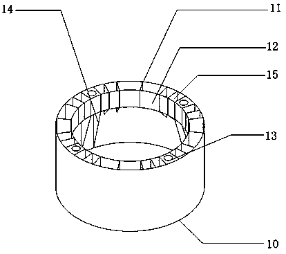
[0041] refer to figure 1 , image 3 with Figure 5 , the second steel cylinder 10 is welded with the second reserved steel sleeve 13 at the four positions corresponding to the upper jacket structure leg pile 4. If the upper jacket is of 3-pipe type, the reserved steel sleeve and its adjacent Parts are also reduced accordingly, the reserved steel sleeves and the upper jacket are arranged at equal intervals along the circular direction of the steel cylinder, the diameter of the second reserved steel sleeve 13 is 2m-3m, and the leg pile 4 and the second reserved steel sleeve The cylinders 13 are connected by grouting, and the end of the second reserved steel sleeve 13 is sealed with a slant plate to avoid hole cleaning. The second reserved steel sleeve 13 adopts a hole-shaped structure. The top and bottom of the second reserved steel sleeve 3 are welded with steel plates and welded with the inner cylinder 12. The length of the second reserved steel sleeve 13 can be 5m- 10m, th...


PUM


Abstract

The invention discloses a novel plug-in steel cylinder wind power base, and relates to the technical field of offshore wind power base. The novel plug-in steel cylinder wind power base comprises an upper jacket structure, a first lower base steel cylinder structure and a second lower base steel cylinder structure, the upper jacket structure comprises a jacket, diagonal supports, a fan connection transition section, leg piles, the lower base steel cylinder structures comprise steel cylinders, transverse trapezoidal ribs are fixed to the inner walls of the steel cylinders at an equidistant distance in the circumferential direction, and reserved steel sleeves matched with the leg piles are arranged on transverse trapezoidal ribs in a penetrating mode. The novel plug-in steel cylinder wind power base is large in base rigidity, high in anti-overturning ability and high in anti-deformation ability, because the jacket is of a transparent structure, the novel plug-in steel cylinder wind powerbase is less loaded by waves and currents, high safety is achieved, the steel cylinders are used as a basic structure, are good in the sinking ability and high in speed and adapt to various geologicalconditions, all elements are prefabricated on land and transported to the construction site for installation, the efficiency is high, and the novel plug-in steel cylinder wind power base is less affected by the weather and can be used for wind power base application under complex sea conditions.

Description

technical field [0001] The invention belongs to the technical field of offshore wind power foundations, in particular to a novel plug-in steel cylinder wind power foundation. Background technique [0002] Wind energy is a clean and environmentally friendly renewable energy. It will not decrease with its own transformation and human utilization. It has the advantages of long-term, periodic and renewable, so wind energy is a real green energy. At present, the main application of wind energy is wind turbine power generation. Using wind power to generate electricity can effectively utilize wind energy. With the large-scale development and utilization of offshore wind energy, the foundation of offshore wind turbines has become another important marine engineering structure, which is increasingly recognized by the country. highly valued. [0003] At present, offshore wind power construction is mainly concentrated in the southeast coastal area. Due to the influence of monsoons and...

Claims


Application Information

Patent Timeline
Patent Type & Authority Applications(China)
IPC IPC(8): E02D27/42E02D27/52
CPCE02D27/425E02D27/525
Inventor 卢永昌王婷婷卢生军王维杰林先炜李家华
Owner CCCC FHDI ENG
Learn More