
Voltage dividing device of ring network cabinet type high-voltage electronic equipment

A technology of electronic equipment and ring main unit, which is applied in the field of electric power, can solve the problems of large lightning strike voltage of the voltage divider, affect the life of the voltage divider, and affect the measurement accuracy, etc., and achieve the effect of reducing the large distortion of the current waveform and reducing the protection level

Pending Publication Date: 2019-11-05
武汉德能电网技术有限公司
View PDF0 Cites 0 Cited by
  • Summary
  • Abstract
  • Description
  • Claims
  • Application Information

AI Technical Summary

Problems solved by technology

[0002] The measurement circuit of the original product is at the same potential as the earth. The primary and secondary stages of the current transformer are subjected to high voltage. The primary stage of the transformer is high voltage, and the secondary stage is low voltage. The stage forms a parasitic current, which affects the measurement accuracy
[0003] The original ring network cabinet products, after the star connection, adopt the grounding scheme at the end, resulting in the voltage divider being subjected to a huge lightning strike voltage during a lightning strike, which affects the life of the voltage divider

Method used


Image

  • Voltage dividing device of ring network cabinet type high-voltage electronic equipment

Examples


Embodiment 1

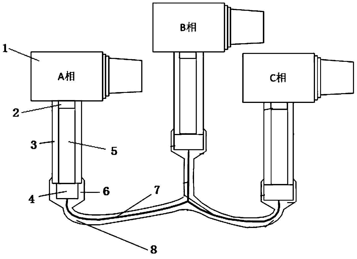
[0017] Example 1: See figure 1 , a voltage dividing device of a ring network cabinet type high-voltage electronic device, including a cable T head 1 and a conductive wire 7, the cable T head 1 has three, and each cable T head 1 is provided with a voltage divider 5 , the outside of the voltage divider 5 is provided with an insulating outer layer 3, the insulating layer 3 insulates the voltage divider 5 from the outside world, the voltage divider 5 plays the role of insulation or sampling, and a tail cover 6 is provided under the voltage divider 5 , the tail cover 6 is a sealing structure, the tail cover 6 is used to seal the lower end of the voltage divider 5, insulate the voltage divider 5 from the outside world, connect the conductive wire 7 to the voltage divider 5, and play an insulating role to the outside, The second circuit 4 in the tail cover 6 is set according to the requirements of different devices, and the voltage dividers 5 under the T-heads 1 of the three cables a...

Embodiment 2

[0019] Embodiment 2, on the basis of Embodiment 1, the exterior of the conductive wire 7 of this design is provided with an insulating outer layer 8 of a flexible connecting wire. Electrically connect the T head 1 tail of the A, B, and C three-phase cables, and insulate the connecting wires. The entire electrical part is completely insulated from the outside to avoid the formation of an electrical path between the phases and the ground.


PUM


Abstract

The invention discloses a voltage dividing device of ring network cabinet type high-voltage electronic equipment, which comprises cable T joints and conductive wires, wherein the number of the cable Tjoints is three, each cable T joint is provided with a voltage divider below, each voltage divider is provided with a tail cover below, and the voltage dividers below the three cable T joints are mutually connected through the conductive wires. According to the voltage dividing device of the ring network cabinet type high-voltage electronic equipment, a measuring and monitoring circuit of split phases is arranged on the high voltage side, so that the voltage at the primary side of a current transformer is enabled to be 0, the parasitic current generated by high voltage is thoroughly removed,and the problem of great measurement errors brought about by current waveform deformation due to great voltage difference between the primary and secondary sides of the transformer is reduced; and thethree phases of voltage dividers adopt a star connection method, the common point is not grounded, and high voltage resistance and insulation are achieved. The lightning protection only needs to be carried out between phases, and the protection between the phases and the ground is not considered. The protection level of lightning protection can be reduced.

Description

technical field [0001] The invention relates to the field of electric power technology, in particular to a voltage dividing device of a ring main unit type high-voltage electronic device. Background technique [0002] The measurement circuit of the original product is at the same potential as the earth. The primary and secondary stages of the current transformer are subjected to high voltage. The primary stage of the transformer is high voltage, and the secondary stage is low voltage. Stages form parasitic currents that affect measurement accuracy. [0003] The original ring network cabinet products, after the star connection, adopt the grounding scheme at the end, which causes the voltage divider to bear a huge lightning strike voltage when lightning strikes, which affects the life of the voltage divider. Contents of the invention [0004] The purpose of the present invention is to provide a voltage dividing device for ring main unit type high-voltage electronic equipmen...

Claims


Application Information

Patent Timeline
Patent Type & Authority Applications(China)
IPC IPC(8): H02H9/04
CPCH02H9/04
Inventor 曾晓强应碧峰
Owner 武汉德能电网技术有限公司
Learn More