
A double-head drilling and tapping machine tool

A technology for processing machine tools and double-head drills, which is applied to metal processing machinery parts, metal processing, metal processing equipment, etc., can solve the problems of high protection level requirements of servo transmission mechanisms, complex mechanisms, waste of raw materials, etc., and achieve pipeline layout Convenience, simplified mechanical structure, and reduced production costs

Active Publication Date: 2017-01-25
北京奥博汽车电子电器有限公司
View PDF8 Cites 0 Cited by
  • Summary
  • Abstract
  • Description
  • Claims
  • Application Information

AI Technical Summary

Problems solved by technology

The existing positioning device cannot meet the production needs of precise positioning, resulting in the generation of a large number of defective products and serious waste of raw materials
And most of the existing machine tools use the drill spindle to move horizontally relative to the machine tool, and the drill spindle moves up and down along the Z axis, so that the workpiece fixture moves back and forth along the X and Y axes on the workbench to drive the workpiece to move to the drill bit that needs to be drilled or tapped. The position of the wire can realize the drilling or tapping process of different parts of the workpiece. This setting makes the X and Y axis servo transmission mechanism of the workpiece fixture located under the workpiece, and the coolant is easy to cool the X, Y axis when spraying the processing surface of the drill bit. The Y-axis servo transmission mechanism causes pollution, which requires a higher protection level for the servo transmission mechanism and a complicated mechanism

Method used


Image

  • A double-head drilling and tapping machine tool
  • A double-head drilling and tapping machine tool
  • A double-head drilling and tapping machine tool

Examples


Embodiment Construction

[0034] The present invention will be further described in detail below in conjunction with the accompanying drawings, so that those skilled in the art can implement it with reference to the description.

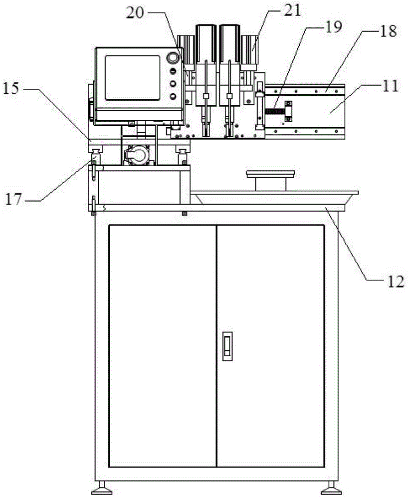
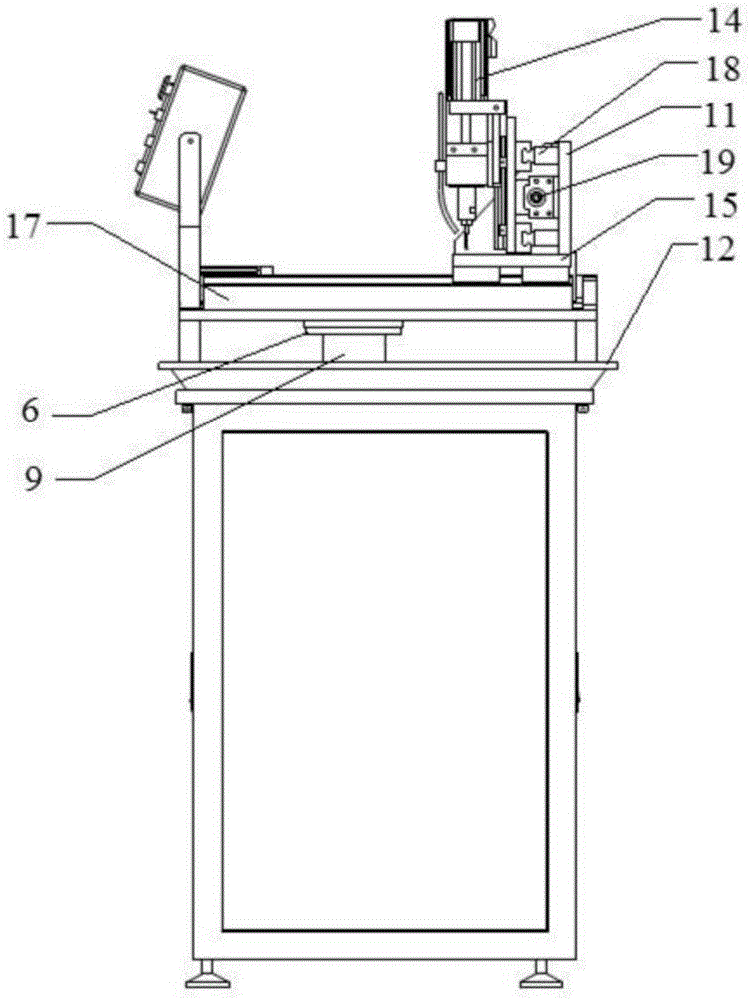
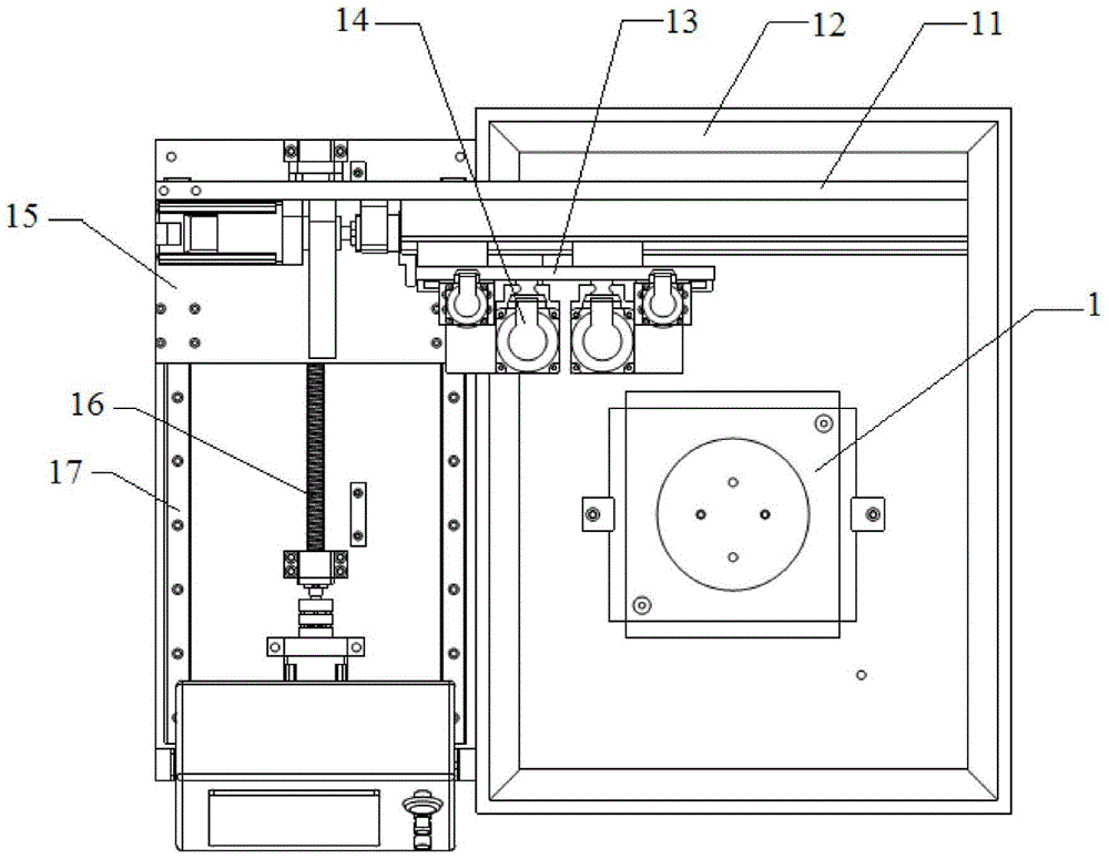
[0035] like figure 1 , figure 2 and image 3 As shown, the present invention provides a double-head drilling and tapping machine tool, which is characterized in that, comprising:

[0036] Workbench 12;

[0037] Floating positioning tool, which is arranged on the workbench 12, and is elastically connected with the workbench 12 laterally, the workpiece to be drilled is fixed on the floating positioning tool, and the hole to be drilled of the workpiece to be drilled is provided with a pit ;

[0038] Two drill bits 14 are arranged side by side above the floating positioning tool and are supported by the workbench 12. The workbench 12 supports the two drill bits 14 along the front-rear direction Y and the left-right direction X through a servo positioning device. and the ver...


PUM


Abstract

The invention relates to a double-head drilling and tapping machining tool. The double-head drilling and tapping machining tool comprises an operating platform, a floating positioning tool and two drill bits, wherein the floating positioning tool is arranged on the operating platform and is transversely and elastically connected with the operating platform; a workpiece to be drilled is fixed on the floating positioning tool; pits are arranged at a hole to be drilled of the workpiece to be drilled; two drill bits are arranged above the floating positioning tool in parallel and are supported by virtue of the operating platform; the operating platform supports the two drill bits to move along the three directions of front-back direction Y, left-right direction X and vertical direction Z by virtue of a servo positioning device. According to the double-head drilling and tapping machining tool, the accurate automatic positioning of machining holes of the workpiece to be drilled can be realized, and the motion of the drill bits on the operating platform along the three directions of front-back direction Y, left-right direction x and vertical direction z is realized; moreover, a mechanical structure is simplified, the drilling or tapping can be realized well based on the reduction of protection levels of an X-axis servo transmission mechanism and a Y-axis servo transmission mechanism, therefore, the production cost can be reduced.

Description

technical field [0001] The invention relates to the technical field of mechanical processing machine tools, in particular to a double-head drilling and tapping machine tool with floating positioning tooling, which is suitable for drilling and tapping of workpieces with bottom holes. Background technique [0002] In the process of automated mass production, the workpiece is positioned and clamped on the workbench with the blank surface, and there will be certain errors in product clamping, but the requirements for the position of the holes to be processed on the workpiece are relatively high. The existing positioning device cannot meet the production needs of precise positioning, resulting in the generation of a large number of defective products and serious waste of raw materials. And most of the existing machine tools use the drill spindle to move horizontally relative to the machine tool, and the drill spindle moves up and down along the Z axis, so that the workpiece fixtu...

Claims


Application Information

Patent Timeline
Patent Type & Authority Patents(China)
IPC IPC(8): B23Q37/00B23Q3/18B23Q5/40B23Q11/10
CPCB23B39/161B23G1/20B23Q3/18B23Q5/40B23Q5/402B23Q11/10
Inventor 董国庆
Owner 北京奥博汽车电子电器有限公司
Learn More