
Diagnosis method and diagnosis system for partial discharge defect type of power equipment

A partial discharge and power equipment technology, applied in the field of partial discharge defect type diagnosis method and diagnosis system, can solve problems such as misjudgment, misleading maintenance strategy, interference, etc., and achieve the goal of improving detection efficiency, reducing technical requirements, and accurate analysis and judgment Effect

Inactive Publication Date: 2019-11-05
STATE GRID HUNAN ELECTRIC POWER +2
View PDF6 Cites 6 Cited by
  • Summary
  • Abstract
  • Description
  • Claims
  • Application Information

AI Technical Summary

Problems solved by technology

[0003] 1. Some partial discharge detection devices do not have a data diagnosis function. The detection process requires the detection personnel to analyze and judge the data by themselves, and the diagnosis of partial discharge often requires long-term experience accumulation to make an accurate judgment. The professional skills of personnel are high, which is not conducive to the development of partial discharge live detection work at the grassroots level of the power grid
[0004] 2. The built-in diagnostic function of some partial discharge detection devices cannot meet the needs of actual field applications
In practical applications, although the defect types in the laboratory can be judged more accurately, in field applications, due to the complex and diverse manifestations of partial discharge defect types, and a large amount of interference, the diagnostic function of the detection device is difficult to accurately identify The type of defect will cause misjudgment during use, which will mislead the judgment of the live inspection personnel and the subsequent maintenance strategy

Method used


Image

  • Diagnosis method and diagnosis system for partial discharge defect type of power equipment
  • Diagnosis method and diagnosis system for partial discharge defect type of power equipment
  • Diagnosis method and diagnosis system for partial discharge defect type of power equipment

Examples


Embodiment Construction

[0030] The present invention will be further described below in conjunction with examples.

[0031] Such as figure 1 As shown, a system for diagnosing partial discharge defects in electrical equipment provided by the present invention includes sequentially connected partial discharge sensors, partial discharge charged detection devices, and a cloud platform. Wherein, the partial discharge sensor is wirelessly or wiredly connected with the partial discharge charging detection device, and the partial discharge charging detection device is connected with the cloud platform through 4G network communication.

[0032] In this embodiment, the partial discharge sensor includes a UHF sensor, a contact ultrasonic sensor, a non-contact ultrasonic sensor, and a high frequency sensor. The present invention uses partial discharge sensors to collect partial discharge data, specifically, UHF sensors collect UHF PRPD / PRPS atlas data, contact ultrasonic and non-contact ultrasonic sensors colle...


PUM


Abstract

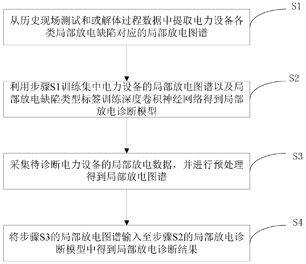
The invention discloses a diagnosis method and diagnosis system for the partial discharge defect type of power equipment. The diagnosis method includes the steps of extracting partial discharge data corresponding to various partial discharge defects of the power equipment from historical data; processing the partial discharge data to obtain a partial discharge atlas corresponding to the partial discharge defects of the power equipment; adopting the partial discharge atlas and partial discharge defect type label of the power equipment to train a deep convolutional neural network to obtain a partial discharge diagnosis model, wherein input data of the partial discharge diagnosis model serves as the partial discharge atlas of the power equipment, output data serves as a partial discharge diagnosis result of the power equipment, and the partial discharge diagnosis result includes whether or not partial discharge and the partial discharge defect type exist; collecting the partial dischargeatlas of the to-be-diagnosed power equipment to be input to the partial discharge diagnosis model to obtain the partial discharge diagnosis result. By means of the diagnosis method, automatic diagnosis of the discharge type is achieved, and the reliability of the diagnosis result is improved by using the neural network.

Description

technical field [0001] The invention belongs to the technical field of partial discharge detection of electric equipment, and in particular relates to a diagnosis method and a diagnosis system of partial discharge defect types of electric equipment. Background technique [0002] With the continuous development of power equipment condition maintenance work, partial discharge, as an important means of power equipment condition detection, is more and more applied to the daily maintenance of power equipment. At present, most of the partial discharge detection work still relies on the operation and maintenance personnel to complete the live detection equipment, and the following problems cannot be effectively solved in the actual operation process by relying solely on personnel for live detection: [0003] 1. Some partial discharge detection devices do not have a data diagnosis function. The detection process requires the detection personnel to analyze and judge the data by thems...

Claims


Application Information

Patent Timeline
Patent Type & Authority Applications(China)
IPC IPC(8): G01R31/12G06K9/00
CPCG01R31/1227G06F2218/12
Inventor 陈骏星溆谢耀恒赵世华叶会生刘赟雷红才黄成军
Owner STATE GRID HUNAN ELECTRIC POWER
Learn More