Air guide gasket and manufacturing method thereof

A gasket and air guide technology, applied in the direction of instruments, measuring forces, measuring devices, etc., can solve the problems of long exhaust sealing time and more residual gas, achieve simple setting method, ensure application range, improve exhaust efficiency and The effect of the exhaust effect

Pending Publication Date: 2019-11-05
CHUANBEI VACUUM TECH BEIJING +1
View PDF0 Cites 0 Cited by
  • Summary
  • Abstract
  • Description
  • Claims
  • Application Information

AI Technical Summary

Problems solved by technology

[0005] Therefore, the object of the present invention is to provide a gas guide gasket to solve the problem of long exhaust sealing time of the differential pressure sensor in the prior art and a large amount of residual gas after sealing.

Method used


Image

  • Air guide gasket and manufacturing method thereof
  • Air guide gasket and manufacturing method thereof
  • Air guide gasket and manufacturing method thereof

Examples


Embodiment 1

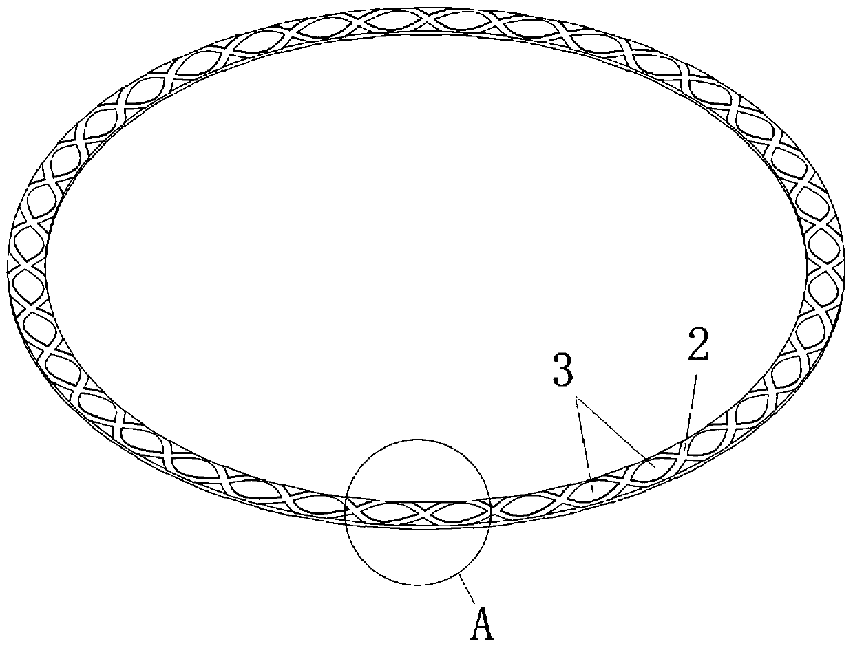
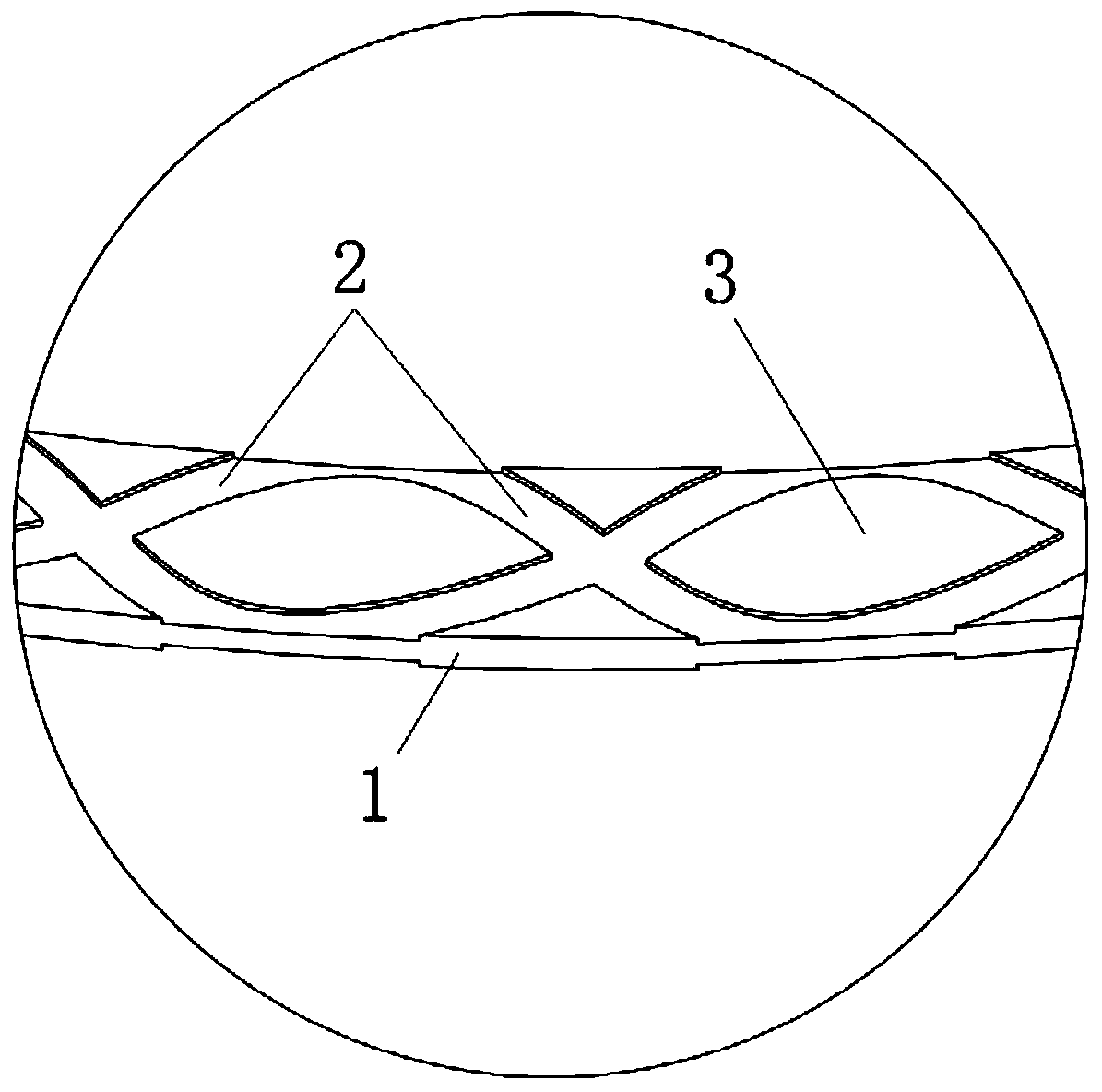
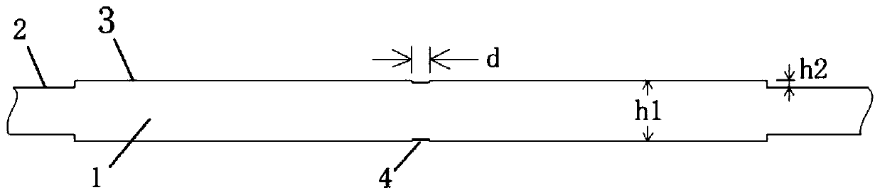
[0040] This embodiment provides a specific implementation of the air guide gasket, such as figure 1 , figure 2 As shown, the gasket body 1 of this embodiment is a conventional ring-shaped gasket, and the gas guiding groove 2 is provided on the upper and lower joint surfaces of the gasket body 1 by laser, and the gas guiding groove 2 has two, It is a sinusoidal shape intersecting with each other, and the air guide groove 2 is used to connect the inner and outer sides of the gasket body 1, so that the inner air of the gasket body 1 can be drawn out in time when vacuuming.

[0041] On the end face of the support step 3 surrounded by the air guide groove 2, there are also two air guide slits 4, the air guide slits 4 are arranged in a cross, and one of the air guide slits 4 communicates with the inner and outer sides of the gasket body 1. On the other side, another air guide slit 4 communicates with the air guide grooves 2 on both sides of the support step 3; through the air guid...

specific Embodiment approach

[0051] This embodiment provides a specific implementation of a method for manufacturing an air guide gasket, including the following steps:

[0052] The first step is to select the thickness of the gasket body 1 to be processed, and select the appropriate thickness of the gasket according to the distance between the two electrodes of the sensor to be adjusted. The specific selection range is 0.05-0.35mm; the thickness of the gasket is selected, It is to adjust the detection signal change of the differential pressure sensor through the micron-scale ultra-thin gasket.

[0053] The second step is to set the gas guide groove 2. On the joint surface of the gasket body 1, adopt methods such as laser, electron beam, chemical corrosion or electrochemical corrosion to set the gas guide groove 2, so that the gasket body 1 The inside and outside are connected.

[0054] The third step is to set the air guide slit 4, on the joint surface of the gasket body 1, on the end face of the support ...


PUM

PropertyMeasurementUnit
Widthaaaaaaaaaa
Thicknessaaaaaaaaaa
Depthaaaaaaaaaa

Abstract

The invention provides an air guide gasket and a manufacturing method thereof, and belongs to the technical field of equipment specially used for manufacturing sensors. The air guide gasket is of an annular structure and comprises a gasket body and air guide grooves, wherein the gasket body is of an annular structure and is provided with an upper junction surface and a lower junction surface, andthe air guide grooves are formed in at least one junction surface of the gasket body and communicated with the inner and outer sides of the gasket body. When the air guide gasket is in use, through the air guide grooves, the inner and outer sides of the gasket body are communicated with each other, on the premise that the original thickness of the gasket body is unchanged, air in an inner ring ofthe gasket body can be quickly and efficiently exhausted during vacuumizing, thus the situation that the air is caught in the annular gasket is avoided, and the exhaust efficiency and exhaust effect of a sensor during ultrahigh vacuum exhaust are improved.

Description

technical field [0001] The invention relates to the technical field of equipment specially used for manufacturing sensors, in particular to an air guiding gasket and a manufacturing method thereof. Background technique [0002] The differential pressure sensor consists of multiple components such as an upper electrode, an insulator, and a lower electrode. When the electrodes are subjected to pressure, the stressed electrodes will be deformed to a certain extent. Therefore, the distance between the upper and lower electrodes will change to a certain extent, thereby changing the detection signal. [0003] In the preparation process of the differential pressure sensor, in order to regulate the distance between the two electrodes of the differential pressure. Usually by replacing one or more hard material spacing washers of different thicknesses, the purpose is to limit the test range of the extremely small differential pressure detection signal. [0004] However, due to the e...

Claims


Application Information

Patent Timeline
IPC IPC(8): G01L1/00G01L13/06
CPCG01L1/005G01L13/06
Inventor 张心强靳毅陈林郜晨希王迪林琳郑旭远雁刘瑞琪李超波
Owner CHUANBEI VACUUM TECH BEIJING
Why Eureka
Try Eureka