
A high-precision infrared radiation measurement method

A technology of infrared radiation and measurement method, which is applied in the field of radiation measurement of infrared systems, can solve the problems of large radiation calibration workload, large error of radiation measurement values, and large workload of infrared system calibration, so as to improve radiation measurement capabilities, The effect of adjusting fineness and flexibility and reducing the workload of calibration

Active Publication Date: 2021-05-11
INST OF OPTICS & ELECTRONICS - CHINESE ACAD OF SCI
View PDF6 Cites 0 Cited by
  • Summary
  • Abstract
  • Description
  • Claims
  • Application Information

AI Technical Summary

Problems solved by technology

[0007] 1. The integration time gear is fixed: limited by factors such as storage capacity and calibration workload, the system can only store multiple sets of fixed integration time coefficient groups, and cannot dynamically select the best integration time, which makes it difficult to give full play to the performance of the infrared system;
[0008] 2. The measurement accuracy is poor: the parameter calculation of the conventional method is grouped and carried out independently according to the integration time, and the correlation between different integration times is ignored. The calibration data is easily affected by the system error and the accuracy is low. Big error in radiation measurement value when bit switching
[0009] 3. The radiation calibration workload is heavy: since the uncalibrated integration time cannot be used in the future use of the system, the system needs to calibrate multiple sets of temperature points under multiple sets of integration times, resulting in a large workload and low efficiency for infrared system calibration. lower

Method used


Image

  • A high-precision infrared radiation measurement method
  • A high-precision infrared radiation measurement method
  • A high-precision infrared radiation measurement method

Examples


Embodiment Construction

[0063] Embodiments of the present invention will be described in detail below in conjunction with the accompanying drawings.

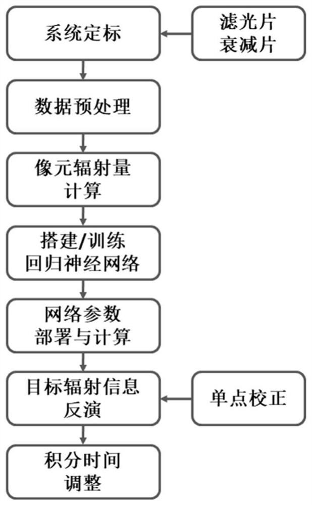
[0064] Such as figure 1 Shown, a kind of high-precision infrared radiation measuring method of the present invention, concrete steps are as follows:

[0065] Step A, system calibration: Calibrate the working point at multiple attenuation slices, integration time, and blackbody temperature points in the system, and obtain multiple frames of raw data of image grayscale response changing with integration time and blackbody temperature.

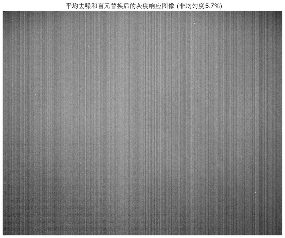
[0066] Step B, data preprocessing: performing average denoising and blind element replacement preprocessing on the multi-frame raw data of each working point. The effect picture after average denoising and blind element processing in this embodiment is as follows figure 2 shown;

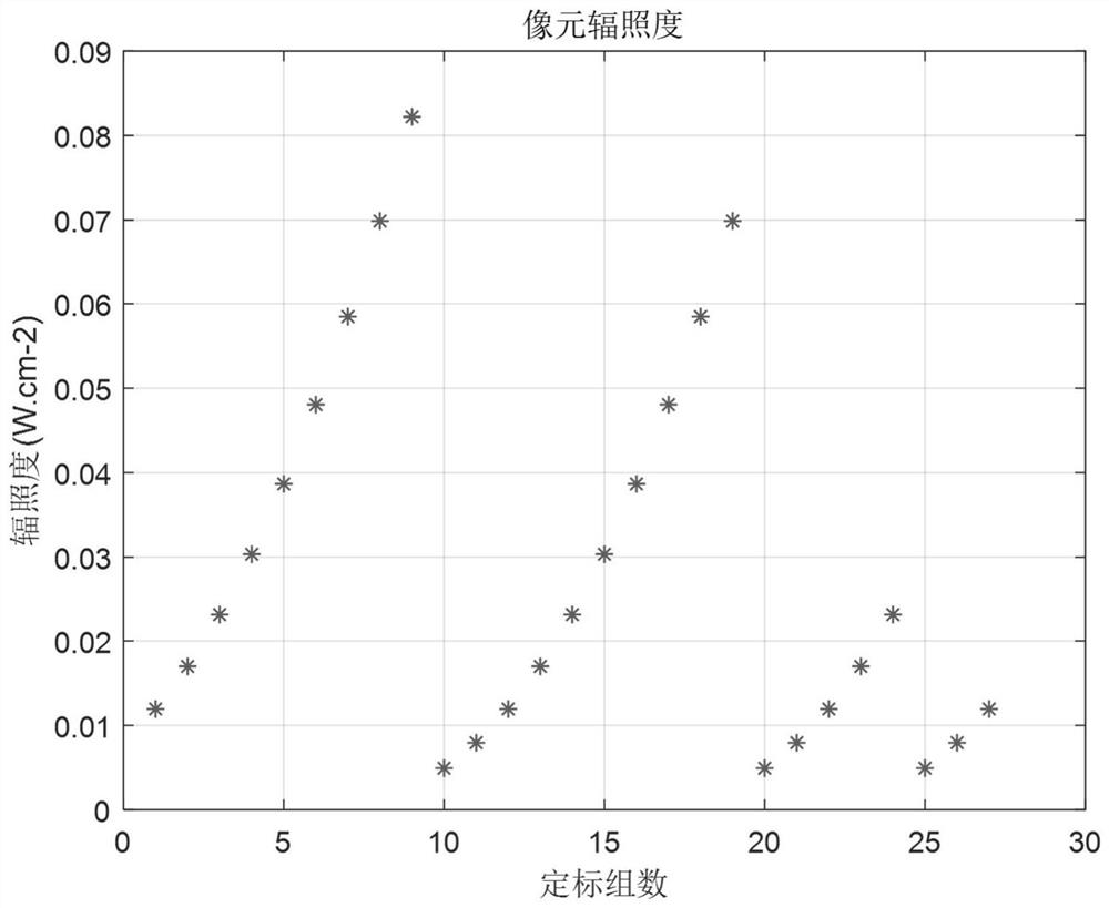
[0067] Step C, calculation of pixel irradiance: taking the pixel irradiance as an example, according to the Planck blackbody radiation form...


PUM


Abstract

The invention discloses a high-precision infrared radiation measurement method, comprising: system working point calibration; original data preprocessing; calculation of theoretical pixel radiation; building and training a regression neural network; using the trained network to predict pixel radiation ; Retrieve the target radiation information according to the pixel radiation amount; during the radiation measurement process, the integration time can be continuously and dynamically adjusted. The invention integrates the calibration data of different integration times and different temperatures into an overall database, learns various parameters reflecting the linear and nonlinear response characteristics of the detector by means of the neural network loss function and the error reverse transmission mechanism, and fully excavates The correlation between the calibration data at different integration times and different temperatures has a stronger ability to resist system random errors in the calibration process, and the trained network has good generalization and nonlinear regression capabilities, and can control Accurately predict the radiation amount of the unscaled integration time and temperature point.

Description

technical field [0001] The invention belongs to the field of infrared system radiation measurement, and in particular relates to a high-precision infrared radiation measurement method. Background technique [0002] Infrared focal plane array belongs to the second-generation infrared imaging device and is one of the core components of the infrared system. It has the advantages of high integration, low noise equivalent temperature difference, and strong detection ability. It is widely used in industry, agriculture, medical treatment, and forest fire prevention. , military and other fields, among which infrared radiation measurement is one of the important applications of infrared focal plane array. [0003] Infrared radiometry requires solving the mathematical regression from detector gray scale response to infrared radiometric information. Infrared radiation information includes radiation intensity, irradiance, radiance, radiation power, equivalent temperature, etc. The the...

Claims


Application Information

Patent Timeline
Patent Type & Authority Patents(China)
IPC IPC(8): G01J5/52
CPCG01J5/485G01J5/80G01J5/53
Inventor 赖雪峰李素钧周金梅任栖峰王宇韩维强廖胜
Owner INST OF OPTICS & ELECTRONICS - CHINESE ACAD OF SCI
Learn More