An observation window lighting device for a ring network cabinet

A technology for lighting devices and observation windows, which is applied to lighting devices, fixed lighting devices, components of lighting devices, etc., can solve the problems of inability to know the state of the switch position, single function, complicated replacement steps, etc. Illumination area, clear observation effect

Active Publication Date: 2020-08-14
CHANGYUAN ELECTRIC TECH
View PDF14 Cites 0 Cited by
  • Summary
  • Abstract
  • Description
  • Claims
  • Application Information

AI Technical Summary

Problems solved by technology

[0002] At present, the working state of most box-type inflatable metal-enclosed switchgear disconnectors on the market is mainly through the interlock transmission of the operating mechanism and the indicator board to indirectly understand the position status of the disconnector inside the gas box. When the interlock fails, the switch position status will be It is not known; a small number of switchgears have viewing windows, but these viewing windows are small and dark inside the air box, it is difficult to observe the internal state of the switch from the window only by natural light, so there is a way to use LED lights to illuminate the window , the LED light is installed in the air box and illuminates its interior, but because the LED light is a vulnerable part, when the traditional lighting device replaces the LED light, the gas inside the air box must be released, and the replacement steps are cumbersome; in addition, the traditional LED lighting The device is only used as a lighting function with a single function

Method used


Image

  • An observation window lighting device for a ring network cabinet
  • An observation window lighting device for a ring network cabinet
  • An observation window lighting device for a ring network cabinet

Examples


Embodiment Construction

[0025] In order to enable those skilled in the art to better understand the solutions of the present invention, the following will clearly and completely describe the technical solutions in the embodiments of the present invention in conjunction with the drawings in the embodiments of the present invention. Obviously, the described embodiments are only It is an embodiment of a part of the present invention, but not all embodiments. Based on the embodiments of the present invention, all other embodiments obtained by persons of ordinary skill in the art without creative efforts shall fall within the protection scope of the present invention.

[0026] In the following, specific examples will be used to describe in detail respectively.

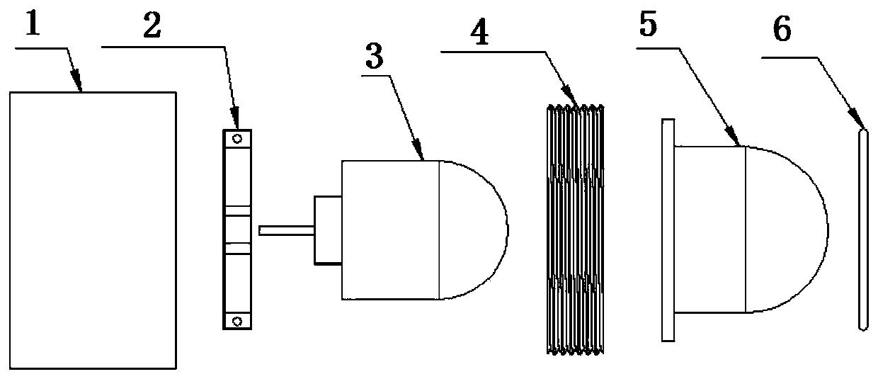
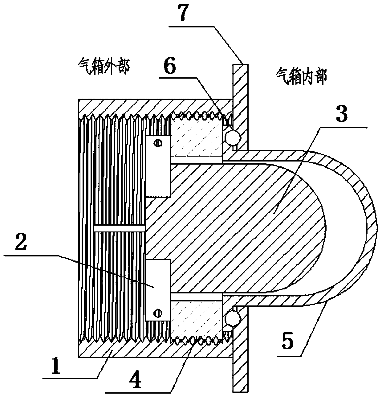
[0027] like Figure 1-4 As shown, an observation window lighting device includes a base 1, a light source 3, a bracket mounting base 4, a light source cover 5 and a fixing plate 7, the fixing plate 7 has an opening, and the base 1 is fixed on the...


PUM


Abstract

The invention relates to an observation window lighting device. The observation window lighting device comprises a base, a light source, a bracket installation base, a light source cover and a fixed plate; the fixed plate is provided with an opening; the base is fixed at one side of the fixed plate, and corresponds to the opening; the base is hollow, and provided with an internal thread; the lightsource cover passes through the interior of the base, and inserted into the opening; the bracket installation base is provided with an external thread matched with the internal thread; the light source cover is tightly pressed on the fixed plate through the bracket installation base, and seals the opening; the bracket installation base is provided with a through hole; the light source is insertedinto the light source cover through the through hole, and detachably fixed on the bracket installation base; the light source cover comprises a flange part; the light source cover is tightly pressedbetween the bracket installation base and the fixed plate through the flange part; a sealing part is also included; and the sealing part is arranged between the flange part and the fixed part. According to the observation window lighting device in the invention, when the light source needs to be replaced, gas in a gas box does not need to be released; and replacement is convenient.

Description

technical field [0001] The invention relates to the field of visible window lighting, in particular to a viewing window lighting device for a ring network cabinet. Background technique [0002] At present, the working state of most box-type inflatable metal-enclosed switchgear disconnectors on the market is mainly through the interlock transmission of the operating mechanism and the indicator board to indirectly understand the position status of the disconnector inside the gas box. When the interlock fails, the switch position status will be It is not known; a small number of switchgears have viewing windows, but these viewing windows are small and dark inside the air box, it is difficult to observe the internal state of the switch from the window only by natural light, so there is a way to use LED lights to illuminate the window , the LED light is installed in the air box and illuminates its interior, but because the LED light is a vulnerable part, when the traditional ligh...

Claims


Application Information

Patent Timeline
Patent Type & Authority Patents(China)
IPC IPC(8): F21S8/00F21V19/04F21V23/04F21V31/00F21Y115/10
CPCF21S8/00F21V19/04F21V23/04F21V31/005F21Y2115/10
Inventor 姚光许永军强卫卢金权欧等财曾荣华陆寒明韩宇
Owner CHANGYUAN ELECTRIC TECH
Why Eureka
Try Eureka