
Pile pulling device and method of shield traversing existing bridge

A technology for shield tunneling and bridges, applied in sheet pile walls, foundation structure engineering, buildings, etc., can solve the problems of difficult construction in narrow spaces, high construction costs, and great impact on the surrounding environment, so as to reduce the difficulty of pulling out piles and achieve efficient construction , On-site adaptability

Pending Publication Date: 2019-11-05
江苏省地质矿产局第三地质大队 +1
View PDF1 Cites 4 Cited by
  • Summary
  • Abstract
  • Description
  • Claims
  • Application Information

AI Technical Summary

Problems solved by technology

[0004] The purpose of the present invention is to solve the technical problems existing in the prior art that the construction in a narrow space is difficult, the impact on the surrounding environment is large, and the construction cost is high, and to provide a device and method for pulling piles across existing bridges with shield tunneling

Method used


Image

  • Pile pulling device and method of shield traversing existing bridge
  • Pile pulling device and method of shield traversing existing bridge
  • Pile pulling device and method of shield traversing existing bridge

Examples


Embodiment 1

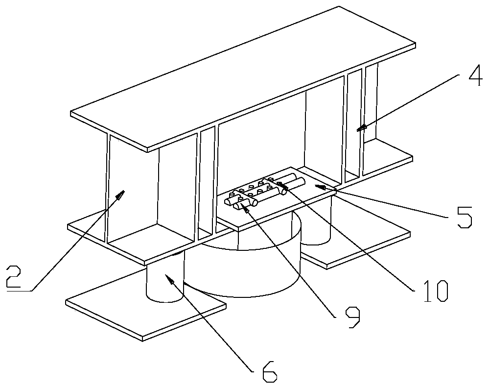
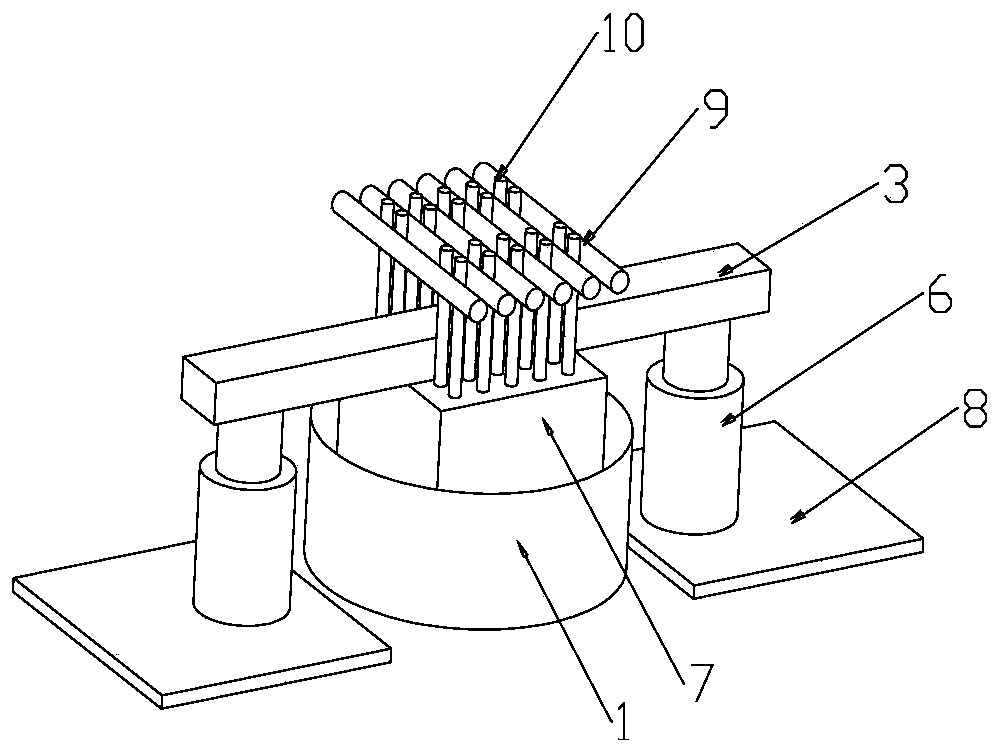
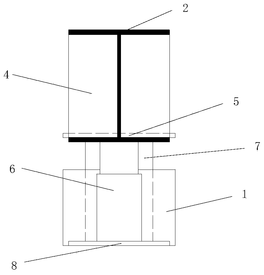
[0050] see Figure 1 to Figure 4 , the present invention is: a shield crossing existing bridge pile pulling device, which includes two parts: a pile head pulling mechanism and a pile body pulling structure; the pile head pulling mechanism includes a steel casing 1, H-shaped steel 2, and several stiffening steel plates And the steel backing plate 5, the inner side of the lower flange of the H-shaped steel 2 and the top contact part of the pile body 7 are symmetrically welded to the steel backing plate 5 along the web, and the main reinforcement 10 of the original pile passes through the bottom plate of the H-shaped steel 2 and the steel backing plate 5 sequentially from bottom to top;

[0051] The pile body removal device comprises a rectangular parallelepiped steel block 3, a jack 6, a steel cushion block 8 and several threaded steel bars 9, and several threaded steel bars 9 are vertically cross-welded with several original pile main reinforcements 10 along the rectangular para...

Embodiment 2

[0067] see Figure 5 to Figure 10 , in order to better achieve the purpose of the present invention, the present invention also provides a shield crossing existing bridge pile pulling device, including two parts: a pile body pulling structure and two oppositely arranged pile head clamping mechanisms;

[0068] The pile body removal structure includes two steel pads 8, two jacks 6 respectively arranged on the two steel pads 8, cuboid steel blocks 3 which are respectively arranged on the tops of the two jacks 6 at both ends, and equidistantly arranged on the top of the middle part of the cuboid steel blocks 3. Several threaded steel bars 9 on the surface are formed;

[0069] The pile head clamping mechanism comprises a base 11 arranged on the top surface of the rectangular parallelepiped steel block 3, a moving guide 12 arranged on the base 11, a main link 13 and an auxiliary link respectively movably connected on the two support arms 120 of the moving guide 12. The linkage 14 i...


PUM


Abstract

The invention provides a pile pulling device and method of a shield traversing an existing bridge and belongs to the technical field of bridge structure reconstruction. By means of the pile pulling device and method of the shield traversing the existing bridge, the technical problems existing in the prior art that construction in small spaces is difficult, has great influence on the surrounding environment and is high in construction cost are solved. The technical scheme of the pile pulling device is that the pile pulling device of the shield traversing the existing bridge comprises two partsof a pile head pullout mechanism and a pile body pullout structure. The pile pulling device and method of the shield traversing the existing bridge have the beneficial effects that segmented upward pulling is performed on a pile body through an H-shaped steel and a cuboid steel block, the pile pulling reliability is guaranteed, efficient construction is also achieved in the limited underground space, influence on superstructures or surrounding buildings is reduced, meanwhile, the method that a steel protection tube is sunk in to perform separation and friction reduction on the pile body and asoil body is adopted, and the pile pulling device and method of the shield traversing the existing bridge have the advantages of being high in stability, fast in construction speed and the like.

Description

technical field [0001] The invention relates to the technical field of bridge structure transformation, in particular to a pile pulling device and method for shield tunneling across existing bridges. Background technique [0002] With the increase of urban population and vehicles, urban subway traffic construction has become the first choice for major cities to solve traffic congestion. Although the layout of the subway lines is in principle to avoid the impact on the original buildings, there are still some subway lines that will pass through the existing bridge pile foundations. Therefore, in order to ensure the normal construction of urban subway lines, existing bridge pile foundations need to be pulled out, and the pile foundations under the bridge can only be pulled out in a very narrow limited space. [0003] According to relevant information, there are relatively few studies on pile extraction in this limited space under the bridge deck, and there is no fully mature ...

Claims


Application Information

Patent Timeline
Patent Type & Authority Applications(China)
IPC IPC(8): E02D9/02
CPCE02D9/02
Inventor 王威卜成杨春杰孙晋晶张盼盼王志华陈炜昀
Owner 江苏省地质矿产局第三地质大队
Learn More