
Deep treatment water supply reconstruction system in safe energy saving overflow mode

An advanced treatment and overflow technology, applied in water/sewage treatment, adsorption water/sewage treatment, water/sludge/sewage treatment, etc. The shortage of land for water plants and other issues can achieve the effect of reducing the volume of storage tanks, highlighting energy saving effects, and reducing water waste

Pending Publication Date: 2019-11-05
SHANGHAI WATER ENG DESIGN & RES INST
View PDF0 Cites 0 Cited by
  • Summary
  • Abstract
  • Description
  • Claims
  • Application Information

AI Technical Summary

Problems solved by technology

[0003] 1. The land of the old water plant is tight. If there are multiple production lines in the original conventional treatment, it is difficult to arrange the advanced treatment process.
[0004] 2. During the transformation period, the impact on the current conventional treatment production line should be as small as possible, but in practice, it is very difficult to realize the water cutoff of each production line in groups, and to realize the pipeline cutover and system switchover in a relatively short period of time
[0005] 3. Due to the different distances between multiple groups of conventional processing production lines and advanced processing production lines, some are far and some are close, when meeting the hydraulic elevation requirements of the farthest group of production lines, it is necessary to connect the conventional processing production lines of each phase to the advanced processing system, and It is very difficult to balance the amount of water transported from each advanced treatment system to each stage of clear water tank
[0006] 4. Safety overflow measures are generally set up for the storage tank in front of the middle lifting pump house, but the overflow water is generally discharged to the rainwater system and finally enters the river, which has the risk of river backflow and wastes water resources. The diameter is large, and the overflow weir also needs a long size, which takes up a lot of space

Method used


Image

  • Deep treatment water supply reconstruction system in safe energy saving overflow mode
  • Deep treatment water supply reconstruction system in safe energy saving overflow mode

Examples


Embodiment Construction

[0027] In order to make the technical means, creative features, goals and effects achieved by the present invention easy to understand, the present invention will be further described below in conjunction with specific illustrations.

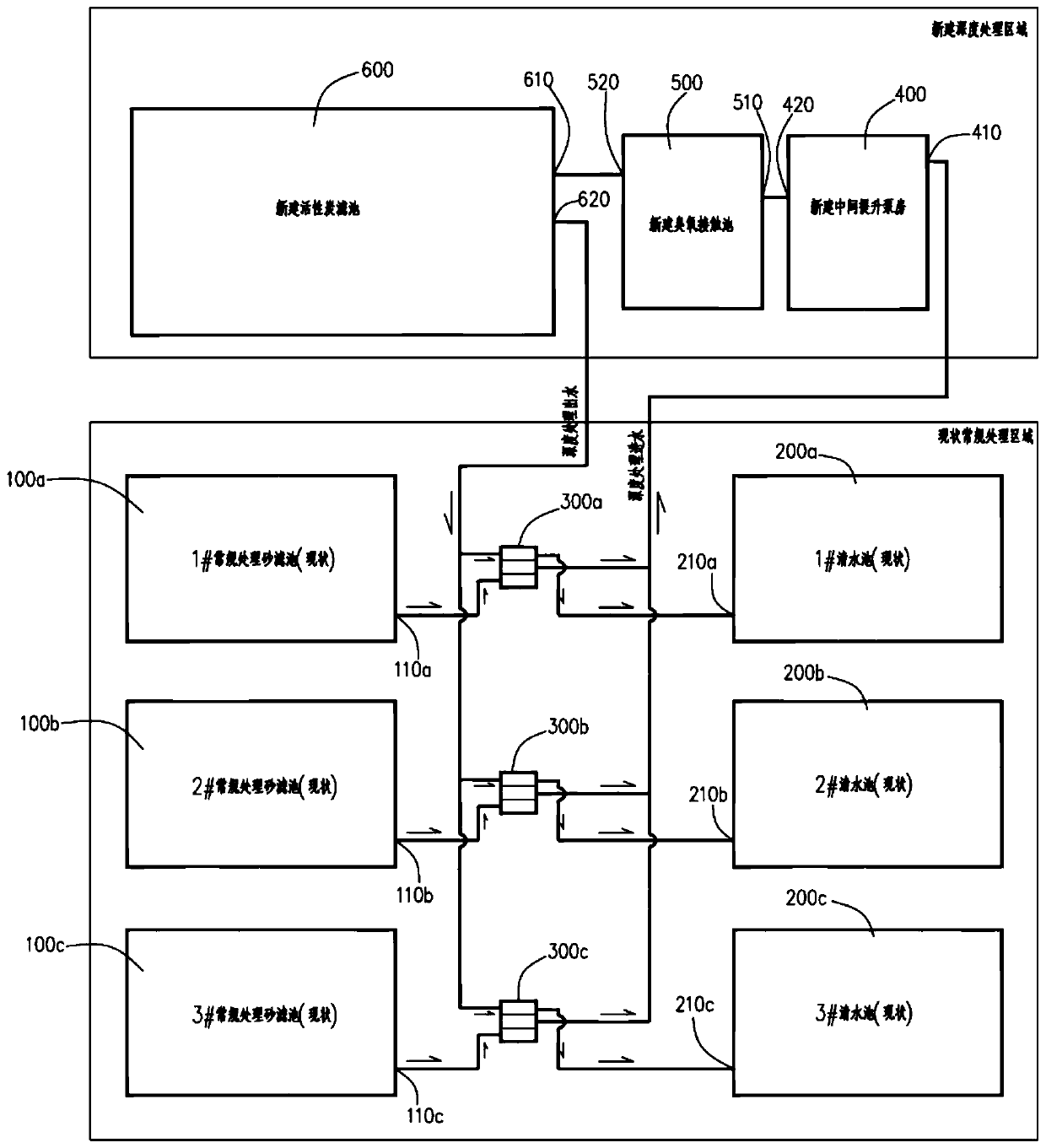
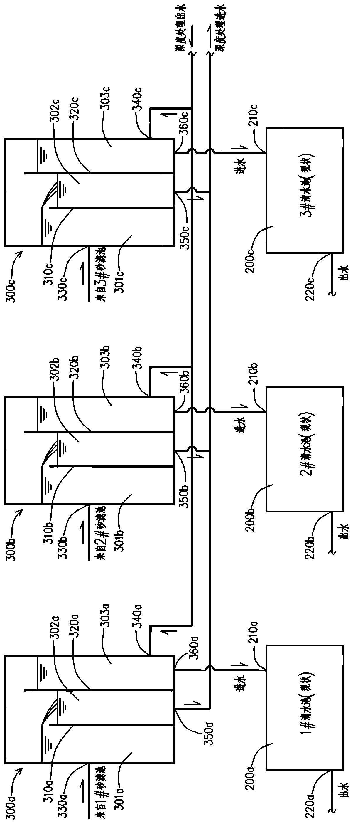
[0028] see figure 1 , shown in the figure is an advanced treatment water supply reconstruction system with a safe and energy-saving overflow mode, including the current conventional treatment sand filter 100a, 100b, 100c, the current clean water tank 200a, 200b, 200c, and the new water level control overflow well 300a, 300b, 300c, newly-built intermediate lifting pump room 400, newly-built ozone contact pool 500 and newly-built activated carbon filter pool 600. In this embodiment, there is a one-to-one relationship between the current conventional treatment sand filter, the current clean water tank, and the newly-built water level control overflow well. set by the quantity.

[0029] Current conventional sand filter tanks 100a, 100b, 100c have ...


PUM


Abstract

A deep treatment water supply reconstruction system in a safe energy-saving overflow mode, disclosed in the invention, includes a plurality of existing conventional treatment sand filters, a pluralityof existing clear water pools, a plurality of new water level control overflow wells, a newly-constructed intermediate lifting pump house, a newly-constructed ozone contact tank and a newly-constructed activated carbon filter, and the plurality of existing conventional treatment sand filters and the plurality of existing clear water pools are connected with the newly-constructed intermediate lifting pump house, the newly-constructed ozone contact tank and the newly-constructed activated carbon filter through the plurality of new water level control overflow wells. The water supply reconstruction system of the invention can realize free switching running of multistage conventional treatment systems and newly-constructed deep treatment systems, is simple, and runs reliably.

Description

technical field [0001] The invention relates to the technical field of advanced treatment water supply systems, in particular to an advanced treatment water supply transformation system with a safe and energy-saving overflow mode. Background technique [0002] In recent years, in order to further improve the quality of water supply and realize the upgrade from "qualified water" to "high-quality water", many water plants using conventional treatment processes are undergoing advanced treatment transformation. The addition of advanced treatment facilities in old water plants often encounters various problems, especially the transformation of multiple sets of conventional water purification production lines into one advanced treatment system. The problems encountered in the advanced treatment transformation of the old water plant are as follows: [0003] 1. The land of the old water plant is tight. If there are multiple production lines in the original conventional treatment, i...

Claims


Application Information

Patent Timeline
Patent Type & Authority Applications(China)
IPC IPC(8): C02F1/00C02F1/28
CPCC02F1/00C02F1/283
Inventor 韦文博
Owner SHANGHAI WATER ENG DESIGN & RES INST
Learn More