A battery clamping device and system for automobiles
A technology for batteries and automobiles, which is applied in the direction of electric power units, power units, motor vehicles, etc. It can solve the problems that batteries cannot be installed, and achieve the effects of efficient installation, avoidance of interference, and convenient posture adjustment
- Summary
- Abstract
- Description
- Claims
- Application Information
AI Technical Summary
Problems solved by technology
Method used
Image
Examples
Embodiment 1
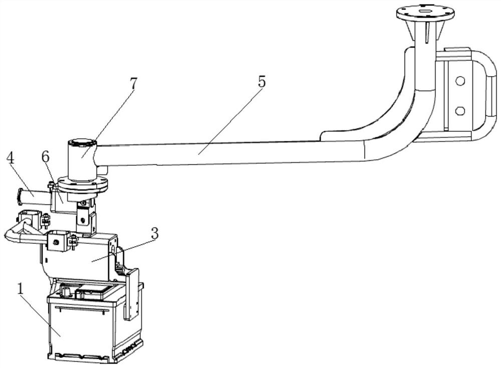
[0046]Seefigure 1 As shown in the present invention, the present invention provides a car battery clamping apparatus for clamping the battery 1 and mounting the battery 1 to the battery mounting area of the vehicle, and the car battery clamping device includes a battery 1. The clamp 3, the horizontal setting rod member 4 and the operating arm 5; one end of the rod member 4 is disposed on the jig 3 and form the connection end 40, the connection end 40 and the gravity of the clamps are substantially in the same lead line, the rod The other end of the 4 extends away from the jig 3 and forms the distal end 41; one end of the operating arm rod 5 is slid on the rod member 4, and can be moved back and forth between the connection end 40 and the distal end 41, operate the arm 5 The other end is used to connect to the robot arm, controlling the movement of the operating arm 5 by the robot arm, capable of automatically clamping the battery 1 and mounting the battery 1.
[0047]Seefigure 2 As s...
Embodiment 2
[0051]The basic content is the same as in Example 1.
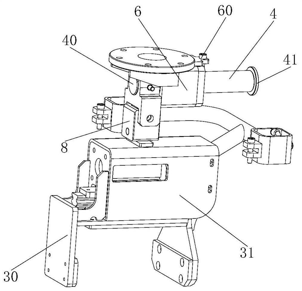
[0052]SeeFigure 4 As shown, the clamp 3 in the second embodiment of the present invention includes a driving device 30 and two jaws 31 disposed on both sides of the driving device 30, and the two jaws 31 form a clamping space 32 for clamping the battery 1. The drive device 30 is connected to the at least one jaw 31 and is used to drive the two jaws 31 near or away from each other. Specifically, the drive device 30 includes a slide rail 300, a fixed block 301, a cylinder 302, and a controller 304, and one end of the slide rail 300 are connected to a jaw 31 in the two jaws 31; fixed block 301 and slide 300 is adapted, the rail 300 is provided on the fixed block 301; the cylinder 302 has a telescopic drive shaft 303 coupled to the rail 300; the controller 304 is connected to the cylinder 302 and is used to control the cylinder 302 drive slide rail 300 along the fixed block 301 moves. When the clamp 3 in the second embodiment of the pr...
Embodiment 3
[0054]The basic content is the same as in Example 1.
[0055]SeeFigure 2-4As shown, the operating arm 5 is slidably arranged on the rod member 4 by a sliding kit 6. The sliding kit 6 of the present invention is a linear bearing, and when the clamping device is converted from the first mounting state to the second mounting state, the rod member 4 is slid in the straight bearing until the linear bearing is located in the straight bearing The distal end 41 of the rod member 4. A positioning pin 60 is provided on the sliding kit 6, and a positioning hole 42 that is adapted to the positioning pin 60 is opened. When the clamping device is in the first mounting state, the positioning pin 60 is inserted into the positioning hole 42, and the operating arm rod 5 is fixed to the connection end 40 of the rod member 4, and the positioning of the operating arm 5 is achieved. When the clamping device is in the second mounting state, the positioning pin 60 is pressed on the outer surface of the distal...
PUM
 Abstract
Description
Claims
Application Information
 - R&D
- Intellectual Property
- Life Sciences
- Materials
- Tech Scout
- Unparalleled Data Quality
- Higher Quality Content
- 60% Fewer Hallucinations
Browse by: Latest US Patents, China's latest patents, Technical Efficacy Thesaurus, Application Domain, Technology Topic, Popular Technical Reports.
© 2025 PatSnap. All rights reserved.Legal|Privacy policy|Modern Slavery Act Transparency Statement|Sitemap|About US| Contact US: help@patsnap.com


