Eureka AIR delivers breakthrough ideas for toughest innovation challenges, trusted by R&D personnel around the world.

Seal head structure part welding dislocation control tool and assembling method

A technology for structural parts and tooling, which is applied in the field of welding and manufacturing of ultra-high-strength steel pressure-bearing structural parts, can solve the problems of dislocation and deformation of circumferential seam welding on the end face of the front head, achieve satisfactory weld quality, reduce welding dislocation deformation, and improve The effect of clamping stability

Inactive Publication Date: 2019-11-05
西安长峰机电研究所
View PDF7 Cites 9 Cited by
  • Summary
  • Abstract
  • Description
  • Claims
  • Application Information

AI Technical Summary

Problems solved by technology

[0003] In order to overcome the deficiencies of the prior art, the present invention provides a head structure welding dislocation control tool and assembly method, by designing the front head argon arc welding welding fixture, using the tool to adjust the assembly function, optimizing the welding process, and adopting a reasonable Assembly positioning method to solve the problem of dislocation and deformation of the circular seam welding of the front end face of an engine

Method used


Image

  • Seal head structure part welding dislocation control tool and assembling method
  • Seal head structure part welding dislocation control tool and assembling method
  • Seal head structure part welding dislocation control tool and assembling method

Examples


Embodiment Construction

[0021] The present invention will be further described below in conjunction with the accompanying drawings and embodiments, and the present invention includes but not limited to the following embodiments.

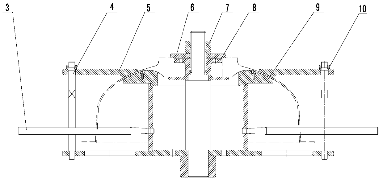
[0022] In order to achieve the purpose of controlling and solving the welding dislocation and deformation of the front head structure of the engine, the present invention designs a tooling fixture. According to the dislocation deformation rule of the front head after welding, when assembling the front joint and the hemisphere, the structure of the tooling itself is used to adjust the butt joint dislocation. Reserve a certain amount of misalignment before, increase the positioning solder joints, and increase the degree of restraint. The assembly positioning method reduces the misalignment deformation after welding.

[0023] figure 2 It is a schematic diagram of the fixture structure, which is mainly composed of a handle (detachable without affecting welding), compression nu...


PUM


Abstract

The invention provides a seal head structure part welding dislocation control tool and an assembling method. The tool comprises a pressing disc, a positioning body assembly, a lining and supporting rods. The positioning body assembly comprises a mandrel, a positioning body and a chassis, a hole is formed in the upper surface of the chassis, the mandrel is arranged in a manner of being perpendicular to the chassis, the positioning body is of a ring structure, the positioning body and the mandrel are coaxially mounted on the chassis, the upper surface of the positioning body is tightly attachedto the hemisphere inner wall profile to be welded, the pressing disc is of an annular structure, the inner hole profile is tightly attached to the hemisphere outer wall profile to be welded, the pressing disc is mounted on the chassis through the multiple supporting rods, and is matched with the positioning body, and the position of the hemisphere is fixed. The lining is a hollow step column, an inner hole is in threaded fit with the mandrel, the upper end penetrates through a front joint inner hole to be matched with a gasket and a fastening nut, and the front joint is fixed to the mandrel. The welding process is optimized, the reasonable assembling positioning method is adopted, and the front seal head end face annular line welding dislocation deforming problem of a certain engine is solved.

Description

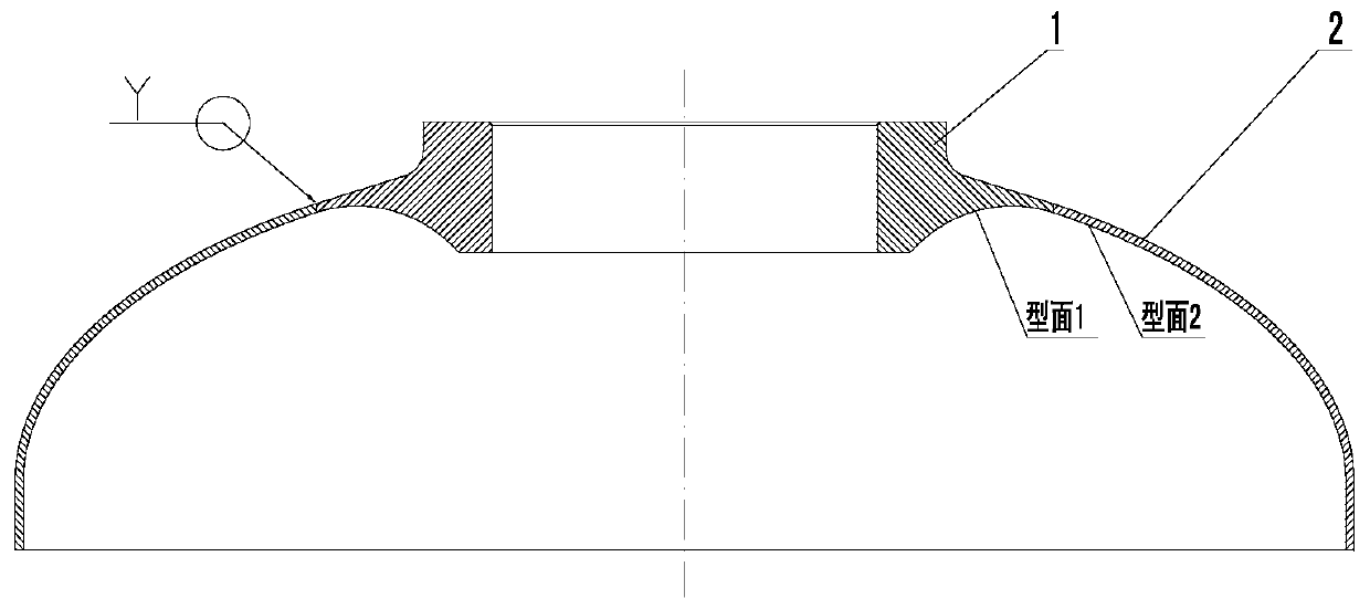
technical field [0001] The invention belongs to the technical field of welding and manufacturing ultra-high-strength steel pressure-bearing structural parts, and relates to a welding dislocation control of a certain engine casing head structural part. Background technique [0002] As an important structural part of an engine, the front head is formed by welding the front joint and the hemisphere. The structure is as follows: figure 1 shown. The quality of the weld seam must not only meet the design index requirements of the pressure-bearing assessment of the combustion chamber shell, but also meet the requirements of the charge design of the engine product. Due to the thin wall thickness of the front joint and the hemisphere, the difference in pre-weld state and processability, assembly and other factors, it is easy to cause weld misalignment and deformation. Utilizing the existing inner support tooling to assemble the engine head structural parts, it is impossible to flex...

Claims


Application Information

Patent Timeline
IPC IPC(8): B23K37/04
CPCB23K37/0426
Inventor 刘涛孟强陈锋胡新郑莉杨立合
Owner 西安长峰机电研究所
Why Eureka
Eureka Blog
Learn More