
Argon arc welding machine with heat dissipation function and working method thereof

An argon arc welding machine and functional technology, applied in the field of argon arc welding machines with heat dissipation function, can solve the problems of inconvenient adjustment of welding torches, long cooling time of pipe fittings, inconvenient operation and use, etc. Heat dissipation effect, convenient welding effect

Active Publication Date: 2019-11-05
SHENZHEN SOLGOO TECH
View PDF6 Cites 9 Cited by
  • Summary
  • Abstract
  • Description
  • Claims
  • Application Information

AI Technical Summary

Problems solved by technology

[0003] In the patent No. CN106112218B, a tube plate argon arc welding machine is disclosed. The welding wire between the wire feeder and the wire guide nozzle on the welding torch of this patent will not be wound on the rotating shaft, but the argon arc welding machine still exists. The defects mentioned above: 1. It does not have the function of fixing the pipe fittings through the clamp driven by the cylinder. Manually fixing the pipe fittings will cause the pipe fittings to loosen easily during the welding process, and deviations will occur, resulting in low welding quality; The function of adjusting the position and then adjusting the accuracy in a small range leads to inaccurate positioning; 3. The position of the welding torch is not easy to adjust, and it is not easy to operate and use. At the same time, the heat dissipation effect is poor, and the cooling time of the pipe fittings is long, resulting in low work efficiency.

Method used


Image

  • Argon arc welding machine with heat dissipation function and working method thereof
  • Argon arc welding machine with heat dissipation function and working method thereof
  • Argon arc welding machine with heat dissipation function and working method thereof

Examples


Embodiment Construction

[0041] The following will clearly and completely describe the technical solutions in the embodiments of the present invention with reference to the accompanying drawings in the embodiments of the present invention. Obviously, the described embodiments are only some, not all, embodiments of the present invention. Based on the embodiments of the present invention, all other embodiments obtained by persons of ordinary skill in the art without creative efforts fall within the protection scope of the present invention.

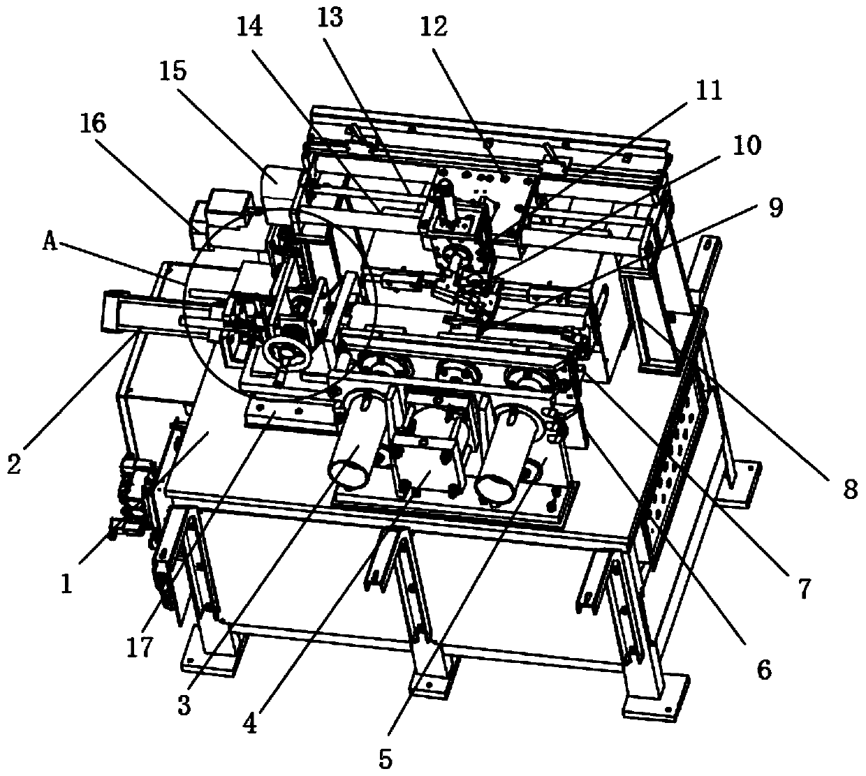
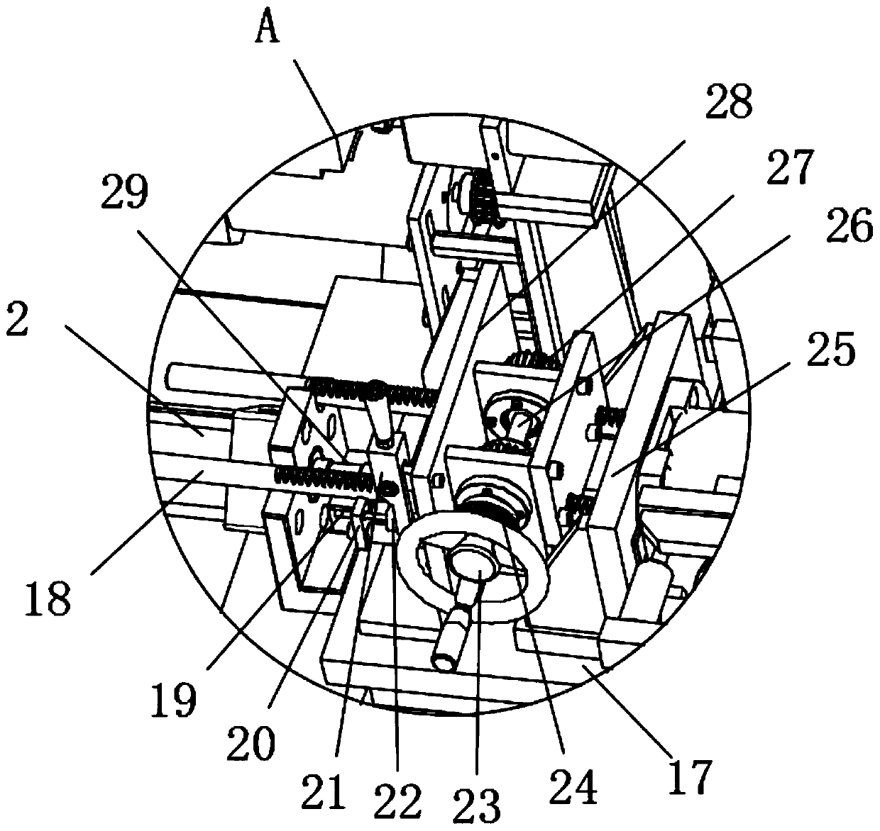
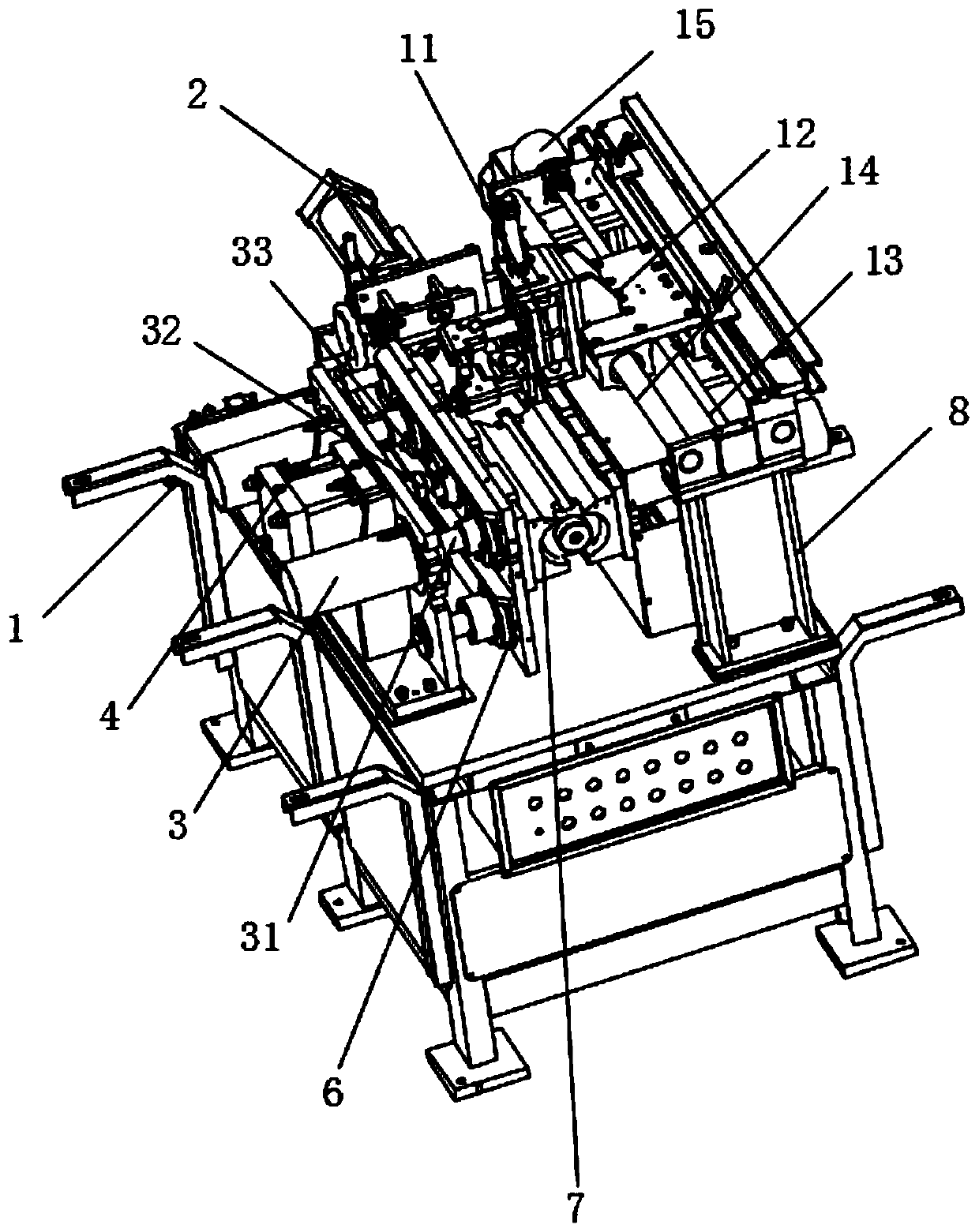
[0042] see Figure 1-9 As shown, a kind of argon arc welding machine with heat dissipation function includes an operation table 1, a fixed plate 5, a bracket 8 and a welding torch 9, and the two ends of the top of the operation table 1 are symmetrically equipped with a fixed plate 5, and the fixed plate 5 A second cylinder 4 is fixedly installed at the center of one side of the cylinder, and a push rod 32 is fixedly installed on the piston rod of the second cylinde...


PUM


Abstract

The invention discloses an argon arc welding machine with a heat dissipation function and a working method thereof. The argon arc welding machine comprises an operating platform, a fixing plate, a support and a welding gun, wherein a second cylinder is fixedly arranged at the center of one side of the fixing plate, and an ejector rod is fixedly arranged on a piston rod of the second cylinder. Theejector rod is driven by the second cylinder to push two movable plates to move towards the middle, a pipe fitting is fixed by two clamps, the pipe fitting can be loosened instead, the pipe fitting isconvenient to fix and loosen, manual fixing is avoided, loosening is easy, labor intensity can be reduced, and working efficiency is improved; a first cylinder drives an air cylinder telescopic rod to push a sliding plate to move rightwards, so that the pipe fitting is pushed to slide rightwards, and the pipe fitting can be roughly adjusted in a large range; the sliding plate is driven by a second lead screw to push the pipe fitting to slide rightwards, accurate adjustment in a small range can be carried out, the pipe fitting can be positioned more accurately, deviation in positioning cannotoccur, welding is easy, and operation is convenient.

Description

technical field [0001] The invention relates to the technical field of argon arc welding machines, in particular to an argon arc welding machine with heat dissipation function and its working method. Background technique [0002] The argon arc welding machine is a machine using argon arc welding, which adopts the arc starting method of high voltage breakdown. Argon arc welding is tungsten inert gas shielded arc welding, which refers to the welding method that uses industrial tungsten or active tungsten as non-melting electrode and inert gas (argon) as protection, referred to as TIG. It is generally used for the welding of thin plates of 6-l Omm and the back welding of single-sided welding and double-sided forming of thick plates. [0003] In the patent No. CN106112218B, a tube plate argon arc welding machine is disclosed. The welding wire between the wire feeder and the wire guide nozzle on the welding torch of this patent will not be wound on the rotating shaft, but the ar...

Claims


Application Information

Patent Timeline
Patent Type & Authority Applications(China)
IPC IPC(8): B23K9/167B23K9/12B23K9/32B23K37/053B23K101/06
CPCB23K9/12B23K9/167B23K9/32B23K37/003B23K37/0533B23K2101/06
Inventor 吴峪李家辉李长友
Owner SHENZHEN SOLGOO TECH
Learn More