
Multi-stage centrifugal pump shell casting forming system

A casting molding and centrifugal pump technology, which is applied in the direction of sending molten metal into the casting mold, casting equipment, manufacturing tools, etc., can solve the problem of low production efficiency of the centrifugal pump shell, which affects the casting effect, casting efficiency, cooling and molding speed Slow down and other problems, to prevent temperature diffusion, improve cooling, and avoid precipitation

Inactive Publication Date: 2019-11-05
ANHUI SANHUAN PUMP
View PDF9 Cites 2 Cited by
  • Summary
  • Abstract
  • Description
  • Claims
  • Application Information

AI Technical Summary

Problems solved by technology

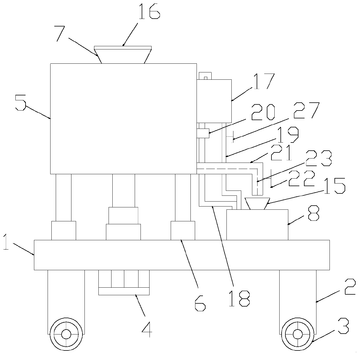
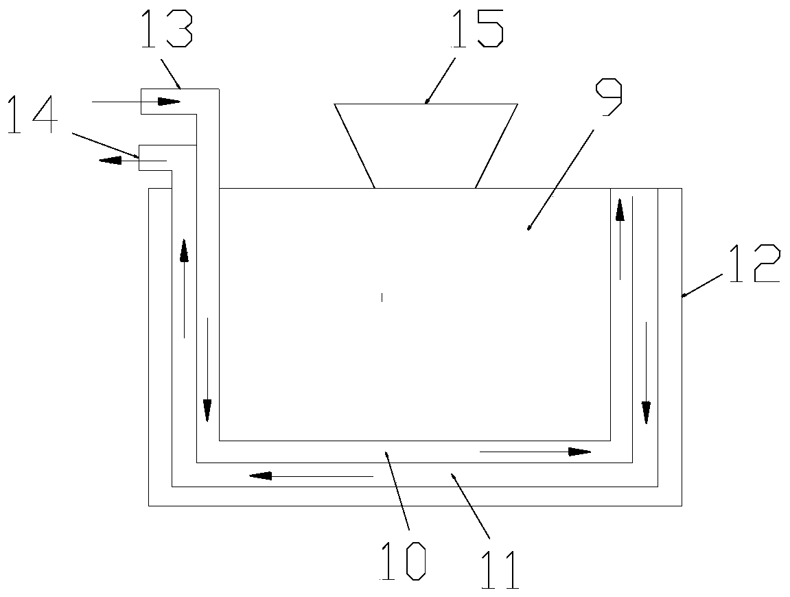
[0002] Centrifugal pump casings are often produced by casting to form a complete whole with good sealing performance and are relatively popular. However, the existing casting and forming systems are prone to local condensation during casting or transfer. , affecting the casting effect and casting efficiency; in addition, after casting, the cooling molding speed is slow, and the production efficiency of the centrifugal pump shell is not high

Method used


Image

  • Multi-stage centrifugal pump shell casting forming system
  • Multi-stage centrifugal pump shell casting forming system
  • Multi-stage centrifugal pump shell casting forming system

Examples


Embodiment Construction

[0020] The following will clearly and completely describe the technical solutions in the embodiments of the present invention with reference to the accompanying drawings in the embodiments of the present invention. Obviously, the described embodiments are only some, not all, embodiments of the present invention. Based on the embodiments of the present invention, all other embodiments obtained by persons of ordinary skill in the art without making creative efforts belong to the protection scope of the present invention.

[0021] In the description of the present invention, it should be noted that the orientation or positional relationship indicated by the terms "vertical", "upper", "lower", "horizontal" etc. is based on the orientation or positional relationship shown in the drawings, and is only In order to facilitate the description of the present invention and simplify the description, it does not indicate or imply that the device or element referred to must have a specific o...


PUM


Abstract

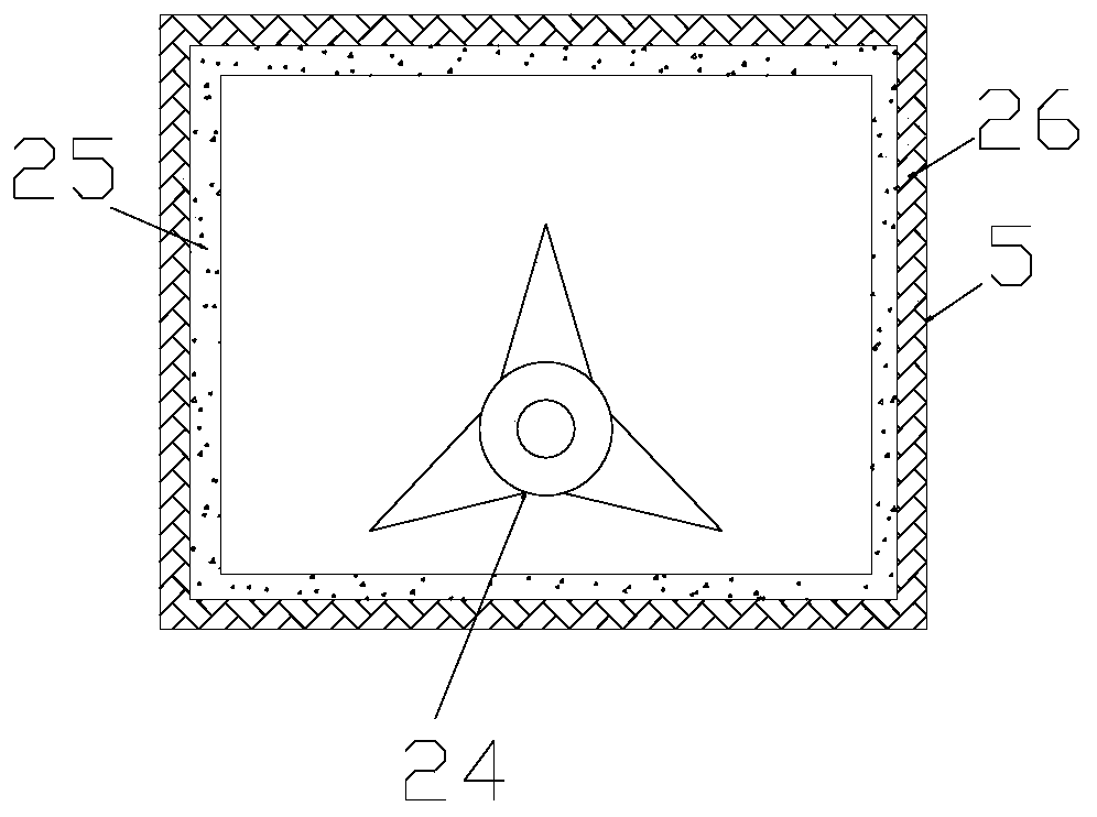
The invention discloses a multi-stage centrifugal pump shell casting forming system. The multi-stage centrifugal pump shell casting forming system comprises a base, a storage tank and a casting cavity, wherein a hydraulic cylinder is arranged at the bottom of the base, a piston rod of the hydraulic cylinder penetrates through the base and is connected with the storage tank, and a water tank is arranged on the outer wall of one side of the storage pipe; a guide pipe is arranged on one side of the bottom of the storage cavity, and a guide valve is arranged on the guide pipe; the casting cavity is arranged on the base and positioned on one side of the storage tank and comprises an inner barrel, a water inlet pipe, a water outlet pipe and an outer barrel, the outer barrel is arranged outside the inner barrel in a sleeving mode, and the water inlet pipe and the water outlet pipe are arranged between the inner barrel and the outer barrel; one end of the water inlet pipe is provided with a water inlet, and one end of the water outlet pipe is provided with a water outlet; and a water guide pipe communicates and is connected with the water inlet, one end, far away from the water inlet, of the water guide pipe communicates and is connected with the bottom of the water tank, a water valve is installed on the water guide pipe, a pump water pipe communicates and is connected with the wateroutlet, one end, far away from the water outlet, of the pump water pipe communicates and is connected with the top of the water tank, and a water pump is installed on the pump water pipe.

Description

technical field [0001] The invention relates to the technical field of centrifugal pump casing production, in particular to a casting molding system for a multistage centrifugal pump casing. Background technique [0002] Centrifugal pump casings are often produced by casting to form a complete whole with good sealing performance and are relatively popular. However, the existing casting and forming systems are prone to local condensation during casting or transfer. , affecting the casting effect and casting efficiency; in addition, after casting, the cooling molding speed is slow, and the production efficiency of the centrifugal pump shell is not high. Contents of the invention [0003] The object of the present invention is to provide a multi-stage centrifugal pump casing casting molding system to solve the problems raised in the above-mentioned background technology. [0004] In order to achieve the above object, the present invention provides the following technical sol...

Claims


Application Information

Patent Timeline
IPC IPC(8): B22D35/04B22D35/06B22D27/04
CPCB22D27/04B22D35/04B22D35/06
Inventor 杨小民
Owner ANHUI SANHUAN PUMP
Learn More