
Arc extinguishing device based on segmented insulator

A segmented insulator and arc extinguishing device technology, which is applied to high-voltage air circuit breakers, electrical components, electrical switches, etc., can solve the problem of arc segmentation under unfavorable working conditions, threatening the safety of the traction power supply system, and successfully extinguishing the arc at the arc angle To improve monitoring efficiency and accuracy, reduce erosion and thermal effects, and improve arc extinguishing efficiency

Active Publication Date: 2019-11-01
SOUTHWEST JIAOTONG UNIV
View PDF6 Cites 0 Cited by
  • Summary
  • Abstract
  • Description
  • Claims
  • Application Information

AI Technical Summary

Problems solved by technology

When the electric locomotive pantograph passes through the section insulator, the current from the catenary of the previous section must be cut off, and the voltage at both ends of the section insulator can reach up to several thousand volts. The arc generated here is often not easy to extinguish. The high temperature ablation effect makes the segments often under unfavorable working conditions
In the existing segmented insulator design, only the arcing effect of the arcing angle is not enough to limit the high voltage and high current arcing at both ends of the arcing angle, and the arc length generated by the pantograph passing through the segmented insulator The ablation effect of time on segmental insulators threatens the safety of traction power supply systems
Moreover, with the development of high-speed and high-power electrified railways, the voltage and current at both ends of the breaker isolator is gradually increasing, which makes it increasingly difficult for the traditional breaker insulator to successfully extinguish the arc.

Method used


Image

  • Arc extinguishing device based on segmented insulator
  • Arc extinguishing device based on segmented insulator

Examples


Embodiment

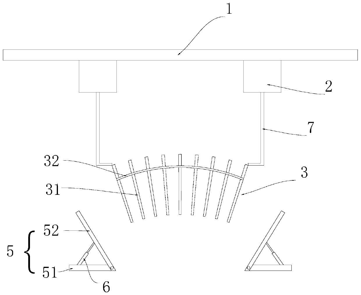
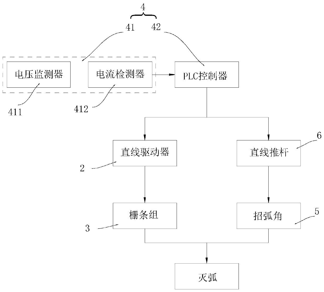
[0024] see Figure 1 to Figure 2 , the present invention includes a suspension cable 1 and two sets of linear actuators 2 arranged on the suspension cable 1 and slidingly connected with the suspension cable 1. The operator can adjust the relative position of the linear actuator 2 and the suspension cable 1 by sliding the linear actuator 2. Between the output ends of the two sets of linear drivers 2 there is a grid bar group 3 for arc extinguishing, and between the linear driver 2 and the grid bar group 3 there is an adjustment suspension wire 7 for connection. Both sides of the bottom end of the grid bar group 3 are provided with an arc angle 5. The grid bar group 3 is composed of a plurality of arc extinguishing grid bars 31 arranged at the output end of the linear driver 2. The shape of the arc extinguishing grid bars 31 is cylindrical and the arc extinguishing grid The material used in bar 31 is high temperature resistant and anti-ablation material. The arc extinguishing g...


PUM


Abstract

The invention discloses an arc extinguishing device based on a segmented insulator, and belongs to the field of segmented insulators. The arc extinguishing device comprises a suspension cable, a linear drive arranged on the suspension cable and slidingly connected with the suspension cable, a grid bar group arranged at the output end of the linear drive and a control group connected to the lineardrive, arcing horns are arranged at the two sides of the bottom end of the grid bar group, the grid bar group is formed by a plurality of arc extinguishing grid bars arranged at the output end of thelinear drive, the arc extinguishing grid bars are provided with fixed frames, the distances between the adjacent arc extinguishing grid bars are gradually increased in a direction close to the lineardrive, and the distances of the arcing horns are gradually increased in a direction close to the linear drive. On the base of ensuring the lateral space of the arcing horns, the arc extinguishing device fully utilizes the longitudinal space of the arcing horns to enhance the de-freeing of the arc, reduces the erosion and heat of the arc on the electrode, protects the segmented insulator device, and ensures the safe running of the high-speed train.

Description

technical field [0001] The invention relates to the field of breaking insulators, in particular to an arc extinguishing device based on a segmented insulator. Background technique [0002] Segmental insulators are important equipment for the same-phase electric segment of the electrified railway catenary. When the equipment is overhauled or fails, it can reduce the scope of power outages and reduce the interference to transportation. It is widely used in marshalling yards, locomotive maintenance yards, passenger hubs and double Line electrified railway. The section insulator has become one of the key equipments in the railway transportation system, and whether the section insulator operates safely and stably has become an important factor for the safe power supply of the catenary. When the electric locomotive pantograph passes through the section insulator, the current from the catenary of the previous section must be cut off, and the voltage at both ends of the section ins...

Claims


Application Information

Patent Timeline
Patent Type & Authority Applications(China)
IPC IPC(8): H01H33/08B60M1/18
CPCB60M1/18H01H33/08
Inventor 高国强李成坤陈少昆谢文汉吴广宁魏文赋杨泽锋
Owner SOUTHWEST JIAOTONG UNIV
Learn More