Fuel cell test system and method
A fuel cell system and fuel cell technology, applied in the direction of measuring electricity, measuring devices, measuring electrical variables, etc., can solve the problems affecting the authenticity of test results, the inability to guarantee the real-time and reliability of the test process, data interaction, logic execution and faults Protection from issues such as lag and jet lag
- Summary
- Abstract
- Description
- Claims
- Application Information
AI Technical Summary
Problems solved by technology
Method used
Image
Examples
Embodiment 1
[0043] See figure 1 , figure 1 It is a schematic structural diagram of a fuel cell testing system provided by an embodiment of the present invention. The fuel cell testing system includes: a lower computer subsystem 10, connected to the fuel cell system to be tested, for generating a real-time test environment according to a configuration file to test the fuel cell system to be tested and generate real-time test data; an upper computer subsystem 20 , connected to the lower computer subsystem 10, for generating configuration files and monitoring the real-time test data.
[0044] It should be noted that the real-time test means that during the test process, the sub-system of the lower computer runs the test steps and test process documents in real time, and there is no time difference in response, so that the test data of the fuel cell system to be tested can be obtained synchronously.
[0045] Specifically, the host computer subsystem 20 includes: a configuration module 201, ...
Embodiment 2
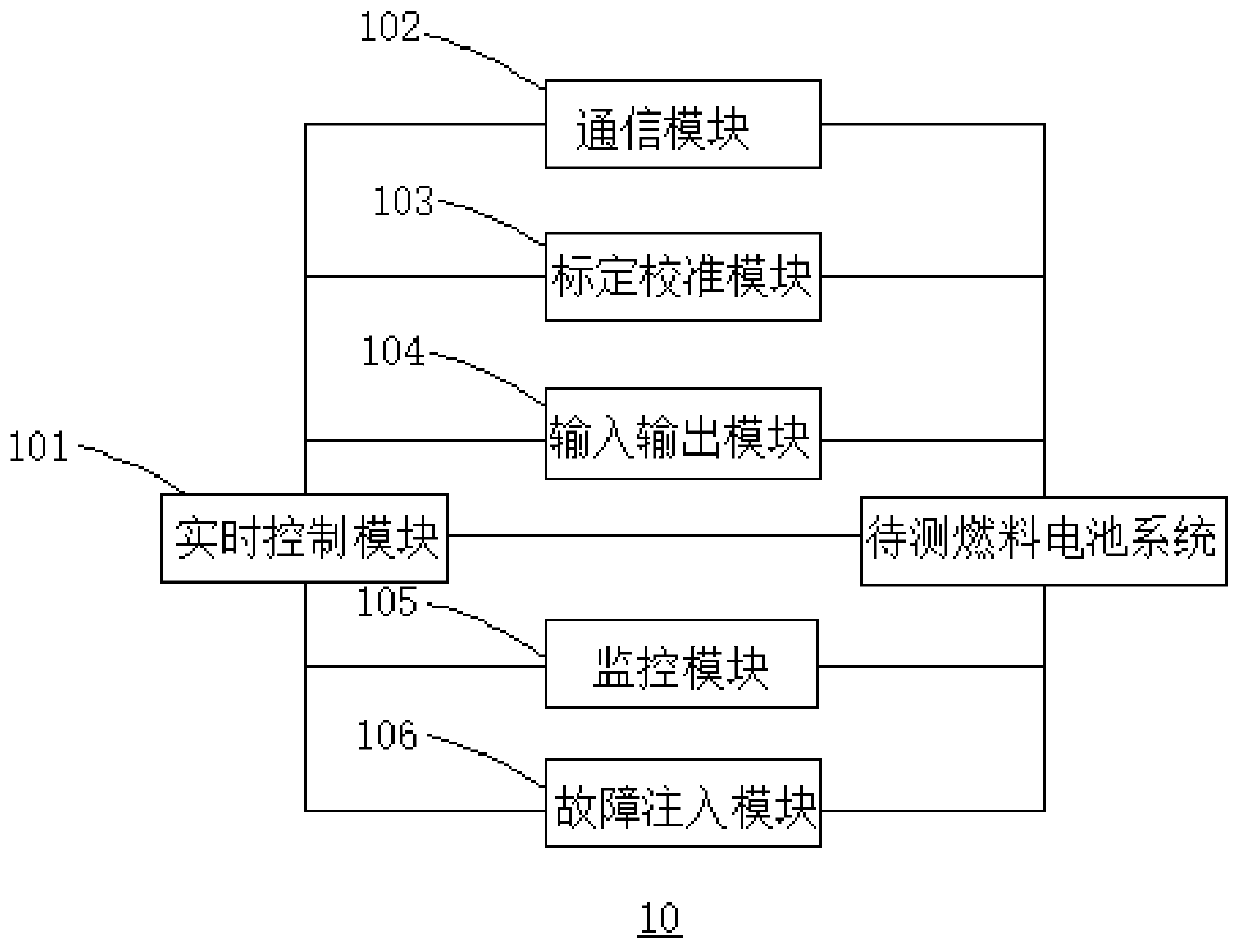
[0050] In this embodiment, on the basis of the first embodiment above, the structure of a fuel cell testing system is introduced in detail. This embodiment includes all the content of Embodiment 1. At the same time, please refer to figure 2 , figure 2 It is a schematic structural diagram of a lower computer subsystem provided by an embodiment of the present invention. The lower computer subsystem 10 includes: a real-time control module 101, a communication module 102, a calibration module 103 and an input-output module 104; wherein,
[0051] The real-time control module 101 is connected with the host computer subsystem 20;
[0052] One end of the communication module 102, the calibration module 103 and the input-output module 104 is connected to the real-time control module 101, the communication module 102, the calibration module 103 and the input-output module 104 The other end of each is connected to the fuel cell system to be tested.
[0053] It should be noted that th...
Embodiment 3
[0090] See Figure 5 , Figure 5 A schematic structural diagram of a real-time test environment provided by the embodiment of the present invention; this embodiment focuses on the detailed description of the real-time test environment of the fuel cell test system on the basis of the above-mentioned embodiments.
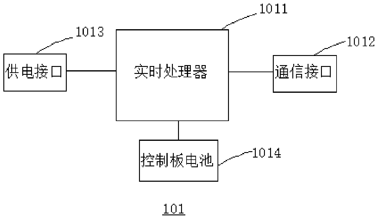
[0091] The real-time test environment includes: industrial Ethernet, I / O interface, CAN interface, RS485 interface, LAN interface, power supply interface 1013, control board battery 1014, ARM core board 10111, ARM memory 10112, insulation monitor 11, water cooler 12 , the fuel cell system to be tested, the electronic load 13 and the fault injection module 106 .
[0092] The host computer subsystem 20, the industrial Ethernet and the ARM core board 10111 are sequentially connected for data transmission between the host computer subsystem 20 and the ARM core board 10111;
[0093] The ARM memory 10112 is set on the ARM core board 10111 for storing test steps and test p...
PUM
 Abstract
Description
Claims
Application Information
 - R&D
- Intellectual Property
- Life Sciences
- Materials
- Tech Scout
- Unparalleled Data Quality
- Higher Quality Content
- 60% Fewer Hallucinations
Browse by: Latest US Patents, China's latest patents, Technical Efficacy Thesaurus, Application Domain, Technology Topic, Popular Technical Reports.
© 2025 PatSnap. All rights reserved.Legal|Privacy policy|Modern Slavery Act Transparency Statement|Sitemap|About US| Contact US: help@patsnap.com


