Engine exhaust temperature inspection system based on ModbusTCP/IP

A technology of exhaust temperature and inspection system, which is applied to thermometers, control/regulation systems, thermometers, etc. that use electric/magnetic components that are directly sensitive to heat, and can solve problems such as low transmission rate, backward networking mode, and short transmission distance and other issues, to achieve the effect of high data transmission rate, easy network opening, and strong reliability

Inactive Publication Date: 2019-11-01
NAVAL UNIV OF ENG PLA
View PDF13 Cites 3 Cited by
  • Summary
  • Abstract
  • Description
  • Claims
  • Application Information

AI Technical Summary

Problems solved by technology

[0002] In industrial workshops, factories and mines, land transportation, navigation and other fields where engines are used, the exhaust temperature of the cylinder reflects the operating status of the engine and is an important monitoring parameter. At present, the problems existing in the engine temperature inspection system are: the networking method is backward and usually adopts Serial communication protocols such as RS232, RS485, and CAN have the disadvantages of low transmission rate and short transmission distance, and the transmission signal is susceptible to external interference. When the monitoring targets are scattered, there are many measurement points, and remote diagnosis is required, it is difficult to network through the above communication methods Realization; the temperature acquisition module often does not have a self-calibration function, and the temperature is prone to drift after a period of continuous operation; the single function of the temperature control software is usually simple real-time display of temperature data, temperature upper and lower limit alarms, no trend curve display, historical data query, Report printing and other functions

Method used


Image

  • Engine exhaust temperature inspection system based on ModbusTCP/IP
  • Engine exhaust temperature inspection system based on ModbusTCP/IP
  • Engine exhaust temperature inspection system based on ModbusTCP/IP

Examples


Embodiment 1

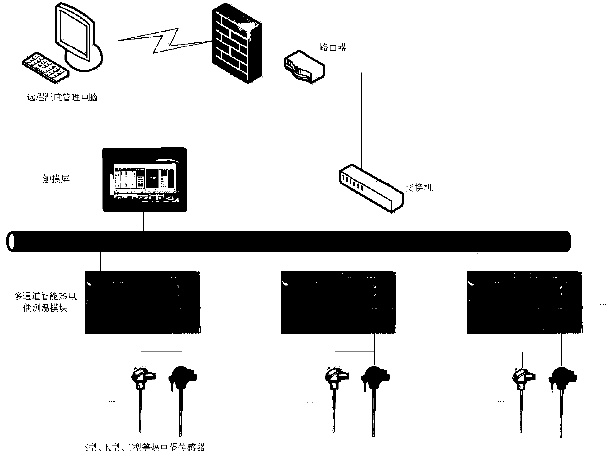
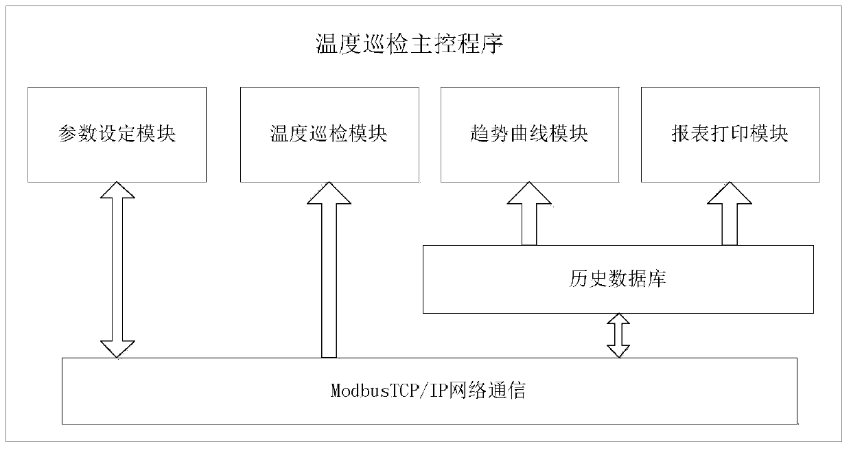
[0030] Such as Figure 1 to Figure 3 As shown, the temperature inspection system described in this embodiment includes a lower multi-channel thermocouple intelligent temperature measurement module and an upper PC or touch screen equipped with a temperature inspection master control program. The temperature measurement module is mainly composed of microcontroller circuit, thermocouple temperature measurement circuit, Ethernet communication circuit, power supply circuit, function setting and storage circuit;

[0031] In this example, if figure 1As shown, the lower multi-channel thermocouple intelligent temperature measurement module and the upper PC or touch screen equipped with the temperature master control program are used as network nodes to form a star-shaped industrial Ethernet network through switches and routers. Directly connect the positive and negative terminals of the thermocouple input signal to the intelligent temperature measurement module through the terminal bl...


PUM


Abstract

The invention belongs to the technical field of inspection instrumentation equipment, and in particular relates to an engine exhaust temperature inspection system based on ModbusTCP / IP comprising a temperature measuring network that uses a lower multi-channel thermocouple temperature measuring module and a host PC or a touch screen equipped with a temperature main control program as nodes, performs connection through 5 types of twisted-pairs and uses a Modbus TCP / IP communication protocol, wherein the multi-channel thermocouple temperature measuring module comprises a microcontroller circuit,a thermocouple temperature measuring circuit, an Ethernet communication circuit and a power supply circuit; the temperature main control program is designed and developed by configuration software tosupport two installation modes of the PC and touch screen. The temperature inspection system provided by the invention has high data transmission rate, high reliability and easy extension of network opening, can conveniently realize remote data communication, has the functions such as distributed operation, remote monitoring and network fault diagnosis, and can be easily promoted to other temperature measurement occasions.

Description

technical field [0001] The invention belongs to the technical field of inspection instrument equipment, and in particular relates to an engine exhaust temperature inspection system based on ModbusTCP / IP. Background technique [0002] In industrial workshops, factories and mines, land transportation, navigation and other fields where engines are used, the exhaust temperature of the cylinder reflects the operating status of the engine and is an important monitoring parameter. At present, the problems existing in the engine temperature inspection system are: the networking method is backward and usually adopts Serial communication protocols such as RS232, RS485, and CAN have the disadvantages of low transmission rate and short transmission distance, and the transmission signal is susceptible to external interference. When the monitoring targets are scattered, there are many measurement points, and remote diagnosis is required, it is difficult to network through the above communi...

Claims


Application Information

Patent Timeline
Patent Type & Authority Applications(China)
IPC IPC(8): G01K7/02G01K7/13G01K15/00G05B19/042H04L29/06
CPCG01K7/021G01K7/13G01K15/005G05B19/0423H04L69/16
Inventor 常广晖郭朝有苏攀
Owner NAVAL UNIV OF ENG PLA
Why Eureka
Try Eureka