
A device and simulation method for simulating projectile movement during bomb delivery

A technology of projectile delivery and movement, which is applied in the field of devices for simulating projectile movement during projectile delivery, can solve the problems of wasting time and manpower, and achieve the effects of improving test efficiency, reducing loading time, and compact structure

Active Publication Date: 2020-06-16
南京理工军邦特种智能装备研究院有限公司
View PDF8 Cites 0 Cited by
  • Summary
  • Abstract
  • Description
  • Claims
  • Application Information

AI Technical Summary

Problems solved by technology

[0003] In the artillery bomb feeding reliability test, after each bomb feeding action is completed, manpower is required to push the projectile out from the direction of the muzzle to the initial position of the bomb feeding, which consumes manpower and wastes time

Method used


Image

  • A device and simulation method for simulating projectile movement during bomb delivery
  • A device and simulation method for simulating projectile movement during bomb delivery
  • A device and simulation method for simulating projectile movement during bomb delivery

Examples


Embodiment Construction

[0030] In the following description, numerous specific details are given in order to provide a more thorough understanding of the present invention. It will be apparent, however, to one skilled in the art that the present invention may be practiced without one or more of these details. In other examples, some technical features known in the art are not described in order to avoid confusion with the present invention.

[0031] In the description of the present invention, it should be noted that the terms "center", "upper", "lower", "left", "right", "vertical", "horizontal", "inner", "outer" etc. The indicated orientation or positional relationship is based on the orientation or positional relationship shown in the drawings, and is only for the convenience of describing the present invention and simplifying the description, rather than indicating or implying that the referred device or element must have a specific orientation, or in a specific orientation. construction and oper...


PUM


Abstract

The invention relates to a device for simulating the ammunition motion in an ammunition delivery process and a simulating method of the device. The device comprises three parts including a basic assembly, a piston assembly and an energy supply assembly. The basic assembly comprises a shell, a cylinder barrel arranged in the shell, an upper end cover and a lower end cover, wherein the upper end cover and the lower end cover are fixedly installed at the two ends of the cylinder barrel respectively; the piston assembly comprises a piston rod which makes reciprocating piston motion in the cylinderbarrel, penetrates through the upper end cover and the lower end cover, and is in clearance fit with the upper end cover and the lower end cover; the energy supply assembly comprises a cavity A oil inlet and a cavity B oil inlet which are formed in the same side of the two ends of the cylinder barrel respectively, hinged-type pipe joints, oil pipe assemblies and a first spring, wherein the hinged-type pipe joints are connected with the cavity A oil inlet and the cavity B oil inlet respectively, the oil pipe assemblies are connected through the hinged-type pipe joints, and the spring sleeves the lower end of the piston rod and is cushioned on the end face of the lower end cover. The device can continuously simulate the ammunition motion in the ammunition delivery process to shorten the loading time, and the test efficiency is improved.

Description

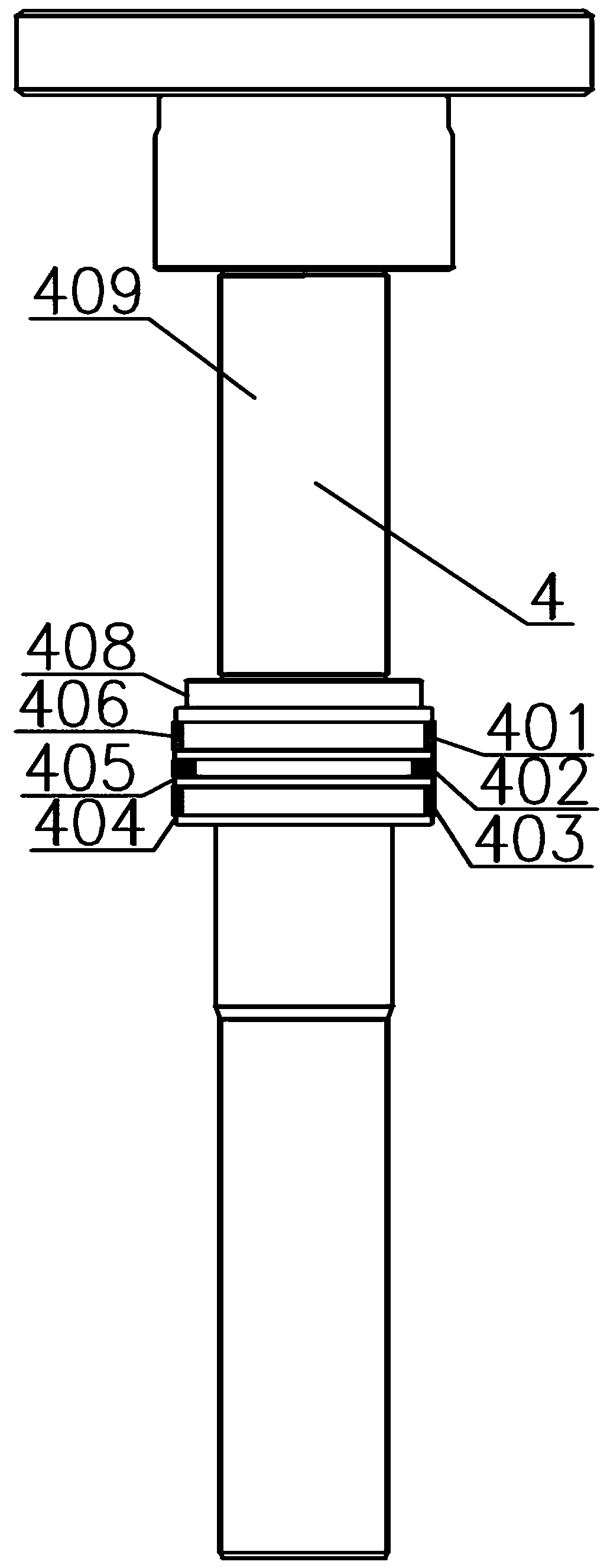
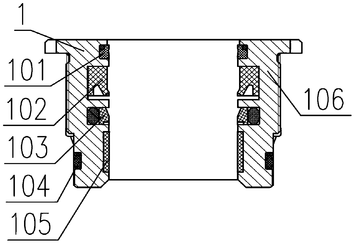
technical field [0001] The invention relates to a hydraulic buffer device, in particular to a device and a simulation method for simulating the movement of projectiles in the process of projectile delivery. Background technique [0002] The key to improving the rate of fire of medium and large caliber artillery is to realize the automatic loading of projectiles. In order to improve the reliability of automatic filling, it is necessary to conduct a large number of filling tests and collect relevant data. [0003] In the artillery bomb feeding reliability test, after each bomb feeding action is completed, manpower is required to pound the projectile out from the direction of the muzzle to the initial position of the bomb feeding, which consumes manpower and wastes time. Contents of the invention [0004] Purpose of the invention: To provide a device for simulating the movement of projectiles during the feeding process and its simulation method, which can continuously simula...

Claims


Application Information

Patent Timeline
Patent Type & Authority Patents(China)
IPC IPC(8): F41A33/00F42B35/00F15B15/14F15B15/20
CPCF15B15/1423F41A33/00F42B35/00
Inventor 陆骏东
Owner 南京理工军邦特种智能装备研究院有限公司
Learn More