
Inclination angle adjustable rocket engine ground test stand frame

A rocket engine and engine support technology, which is applied in the direction of rocket engine devices, machines/engines, mechanical equipment, etc., can solve the problems of damage and danger of the oxidant storage tank, and achieve the effect of ensuring the launch attitude

Inactive Publication Date: 2019-11-01
NORTHWESTERN POLYTECHNICAL UNIV
View PDF6 Cites 12 Cited by
  • Summary
  • Abstract
  • Description
  • Claims
  • Application Information

AI Technical Summary

Problems solved by technology

The thrust test device disclosed in the paper is not suitable for effective thrust measurement of solid-liquid hybrid engines. According to its design structure, the oxidant supply pipeline must directly participate in thrust transmission in the axial direction during the test process. However, due to the high pressure characteristics of the oxidant storage tank And it is a relatively weak part, so it is easy to damage the oxidant storage tank during the thrust transmission process and cause danger

Method used


Image

  • Inclination angle adjustable rocket engine ground test stand frame
  • Inclination angle adjustable rocket engine ground test stand frame
  • Inclination angle adjustable rocket engine ground test stand frame

Examples


Embodiment 1

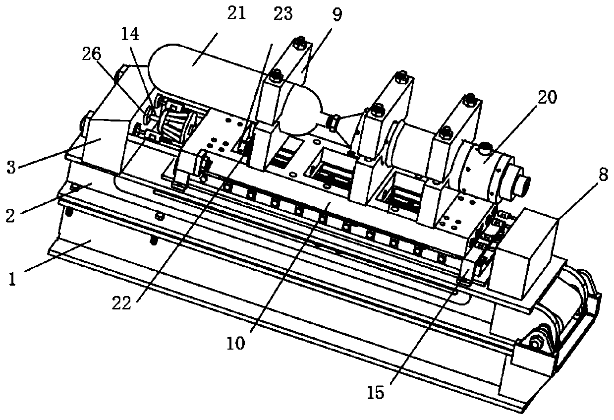
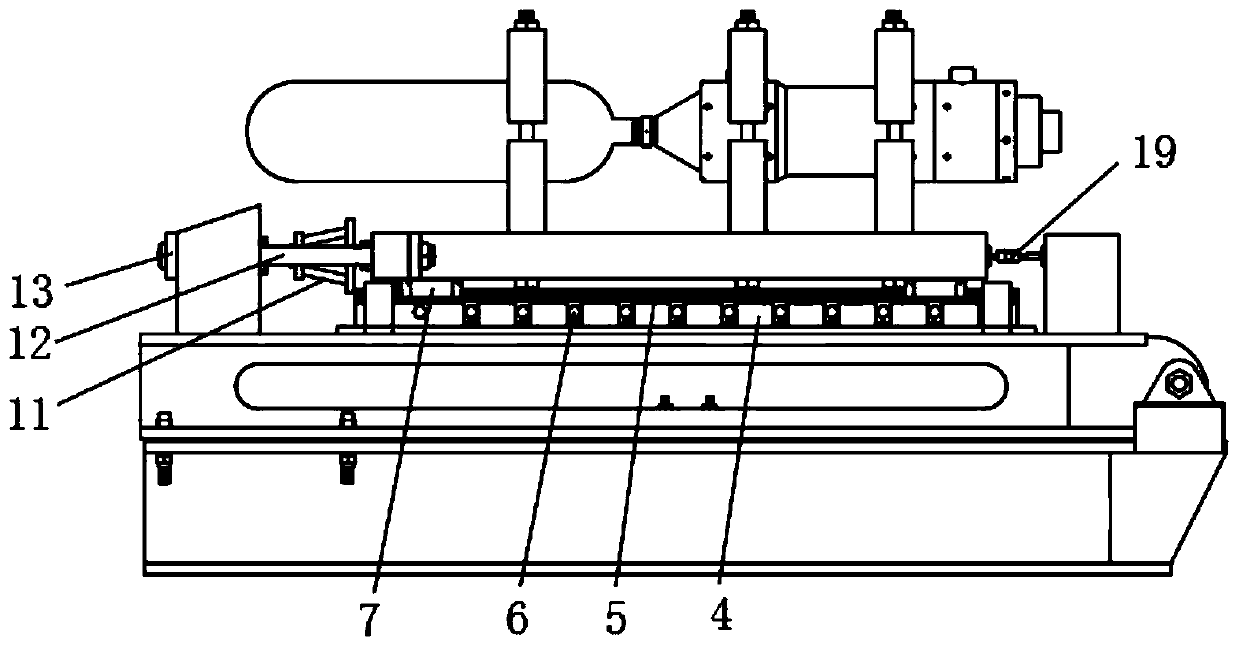
[0063] Horizontal thrust testing of solid rocket motors. Fix the guide rail 5 on the guide rail fixing platform 4 with hexagonal bolts, lock the bolts with the specified torque, and fix the guide rail lateral fixing plate 6 on the guide rail fixing platform 4 with hexagonal screws to limit the tangential direction of the guide rail 5 during the test. To move, use screws to connect and fix the moving frame 10 with the rolling slider 7. The engine bracket 9 is assembled on the moving frame 10, the position is adjusted to suit the size of the experimental engine 20 and fixed with the experimental engine 20 by bolts. The limit frame 15 is fixed on the moving frame 10 by bolts, and the position is adjusted before fixing so that the rolling slider 7 can only move along the thrust direction of the engine. At the same time, a support rod 19 is set between the bearing pier 3 and the movable frame 10 to prevent the movable frame 10 from moving and colliding with the thrust sensor 26 . ...

Embodiment 2

[0066] Vertical thrust test of solid-liquid hybrid rocket motor. Fix the guide rail 5 on the guide rail fixing platform 4 with hexagonal bolts, lock the bolts with the specified torque, and fix the guide rail lateral fixing plate 6 on the guide rail fixing platform 4 with hexagonal screws to limit the tangential direction of the guide rail 5 during the test. To move, use screws to connect and fix the moving frame 10 with the rolling slider 7. The oxidant storage tank 21 is connected with the experimental engine 20 by thread fit, so that the experimental engine 20 and the oxidant storage tank 21 form a solid whole. The engine bracket 9 is installed on the moving frame 10, and the adjusted position is adapted to the overall size of the engine and fixed by bolts. The limit frame 15 is fixed on the moving frame 10 by bolts. The support rod 19 is fixed on the support rod fixing seat 8 by bolts, and the height of the support rod 19 is adjusted so that the plane of the support rod ...

Embodiment 3

[0069] Inclined thrust testing of solid rocket motors. Fix the guide rail 5 on the guide rail fixing platform 4 with hexagonal bolts, lock the bolts with the specified torque, and fix the guide rail lateral fixing plate 6 on the guide rail fixing platform 4 with hexagonal screws to limit the tangential direction of the guide rail 5 during the test. To move, use screws to connect and fix the moving frame 10 with the rolling slider 7. The engine bracket 9 is installed on the moving frame 10, and the adjusted position is adapted to the overall size of the engine and fixed by bolts. The limit frame 15 is fixed on the moving frame 10 by bolts. The support rod 19 is fixed on the support rod fixing seat 8 by bolts, and the height of the support rod 19 is adjusted so that the plane of the support rod 19 is in contact with the plane of the moving frame 10 . At the same time, a support rod 19 is set between the bearing pier 3 and the movable frame 10 to prevent the movable frame 10 fr...


PUM


Abstract

The invention relates to an inclination angle adjustable rocket engine ground test stand frame, and belongs to the technical field of rocket engine thrust tests. The inclination angle adjustable rocket engine ground test stand frame comprises a stand frame supporting device, a thrust transmitting device, a guide rail assembly, a force bearing pier, a guide rod and an engine support, wherein the stand frame supporting device is horizontally arranged, the engine support is fixed at the top of the stand frame supporting device through the guide rail assembly, and the force bearing pier is fixed on one side of the upper end surface of the stand frame supporting device and is connected with the thrust transmitting device. According to the inclination angle adjustable rocket engine ground test stand frame, a hydraulic rod of the stand frame supporting device is used for adjusting the angles of rotating frames, so that different test inclination angles of an engine are achieved, horizontal, vertical and inclined thrust measurement of the engine can be realized, and the test attitude and the emission posture of the engine can be consistent; and meanwhile, effective thrust measurement can be carried out on the rocket engines with different flight postures, the operation is convenient, the advantages of low cost, short flow, high efficiency, convenience and the like are achieved, and large-scale industrial application is easy to implement.

Description

technical field [0001] The invention belongs to the technical field of rocket engine thrust testing, and in particular relates to a rocket engine ground test stand with an adjustable inclination angle. Background technique [0002] The rocket engine is the power device of various missiles and spacecraft, and the thrust is the core technical parameter that reflects the performance of the rocket engine. The change of its size with time directly affects the outer ballistic characteristics of the rocket. Engine thrust can be obtained by calculation and experimental tests, but the premise of theoretical calculation is that characteristic parameters such as characteristic velocity efficiency and nozzle efficiency are known, and these parameters are difficult to obtain, resulting in an inability to accurately predict thrust. Therefore, the engine can be obtained through ground heat test Thrust is the most reliable. Thrust bench is a necessary device for thrust test. Its design str...

Claims


Application Information

Patent Timeline
IPC IPC(8): F02K9/96
CPCF02K9/96
Inventor 刘林林陈泽斌胡松启
Owner NORTHWESTERN POLYTECHNICAL UNIV
Learn More