
Exhaust treatment device for diesel engine

A technology of exhaust gas treatment device and diesel engine, which is applied in the direction of electronic control of exhaust gas treatment device, diagnosis device of exhaust gas treatment device, exhaust device, etc.

Active Publication Date: 2019-11-01
KUBOTA CORP
View PDF15 Cites 0 Cited by
  • Summary
  • Abstract
  • Description
  • Claims
  • Application Information

AI Technical Summary

Problems solved by technology

[0004] In Patent Document 1, even when the clogging state of the DPF with ash changes and the pressure loss of the DPF is improved even after the differential pressure reaches a predetermined threshold value, the notification of the ash accumulation is unconditionally performed, and therefore, ash may be emitted. Unnecessary alerts pile up

Method used


Image

  • Exhaust treatment device for diesel engine
  • Exhaust treatment device for diesel engine
  • Exhaust treatment device for diesel engine

Examples


Embodiment Construction

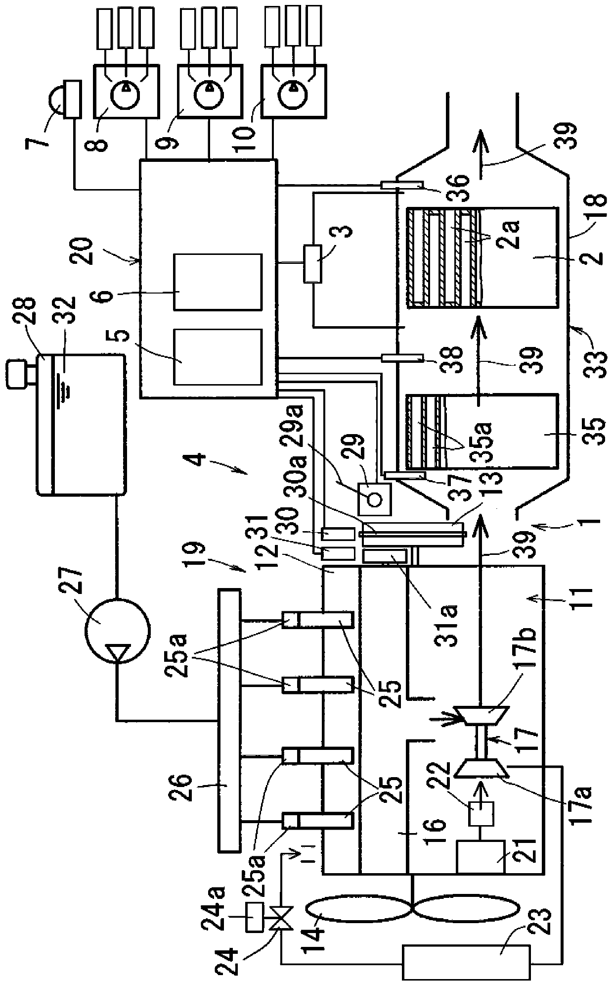
[0026] Figure 1 to Figure 4 It is a figure explaining the engine of embodiment of this invention, and in this embodiment, the vertical water-cooled in-line four-cylinder diesel engine provided with an exhaust gas treatment apparatus is demonstrated.

[0027] The outline of this engine is as follows.

[0028] Such as figure 1 As shown, the engine has: a cylinder block 11; a cylinder head 12 assembled on the top of the cylinder block 11; a flywheel 13 arranged at the rear of the cylinder block 11; an engine cooling fan 14 arranged at the front of the cylinder block 11; An intake manifold (not shown) on one lateral side of the cylinder head 12; an exhaust manifold 16 arranged on the other lateral side of the cylinder head 12; a supercharger 17 connected to the exhaust manifold 16; The exhaust treatment tank 18 on the exhaust gas downstream side of the supercharger 17 ; the fuel supply device 19 ; and the electronic control device 20 .

[0029] The outline of the suction devic...


PUM


Abstract

There is provided an exhaust treatment device for a diesel engine that can prevent unnecessary alarm for ash deposition from being issued. In the exhaust treatment device, a timer measures integratedtime IT of a state of non-regenerative operation which ranges from an end of DPF regeneration to a next time point where the differential pressure reaches a regeneration request value; a counter acquires the short interval count IC, if the integrated time IT is a short interval shorter than a predetermined decision time; and an alarm device issues an alarm, if the consecutive short interval countIC reached a predetermined plural necessary count for alarm. A short interval count IC having been already acquired is preferably reset to 0, if the integrated time IT of the state of non-regenerativeoperation is a long interval not shorter than a predetermined decision time, before the short interval count IC reaches a predetermined necessary count for alarm.

Description

technical field [0001] The present invention relates to an exhaust gas treatment device for a diesel engine, and more particularly, to an exhaust gas treatment device for a diesel engine that prevents unnecessary alarms from ash accumulation. Background technique [0002] Conventionally, as an exhaust treatment device for a diesel engine, there is a device that has a DPF (Diesel Particulate Filter) arranged in an exhaust path, a differential pressure sensor that detects the pressure difference between an exhaust inlet and an exhaust outlet of the DPF, And the ash cleaning request notification device notifies the ash cleaning request when the differential pressure detected by the pressure difference sensor reaches a predetermined threshold value (for example, refer to Patent Document 1). [0003] Patent Document 1: Japanese Unexamined Patent Publication No. 2011-202573 (refer to figure 1 , figure 2 ). [0004] In Patent Document 1, even when the clogging state of the DPF ...

Claims


Application Information

Patent Timeline
Patent Type & Authority Applications(China)
IPC IPC(8): F01N3/021F01N3/023F01N11/00F01N13/00
CPCF01N3/021F01N3/023F01N11/002F01N11/00F01N13/00F01N2550/00F01N9/002F02D41/029F02D41/22F02D2200/0812B01D46/0086B01D46/446B01D2279/30F01N2560/08F01N2900/1406Y02T10/12Y02T10/40F01N2900/0421
Inventor 井上胜支舩木耕一藤原正德久野完喜多健太郎吉田勇树
Owner KUBOTA CORP
Learn More