Automatic stacking device for logistics

An automatic stacking and palletizing device technology, applied in the stacking of objects, unstacking of objects, transportation and packaging, etc., can solve the problems of feed bag offset, economic loss, collapse, etc., to achieve stability and balance, improve Work efficiency, improve the effect of stability

Active Publication Date: 2019-10-29
姚伟波
View PDF11 Cites 0 Cited by
  • Summary
  • Abstract
  • Description
  • Claims
  • Application Information

AI Technical Summary

Problems solved by technology

[0002] With the development of modern industry, human beings are gradually replacing labor with mechanical tools. Palletizing lines are widely used in the transportation and palletizing of bagged materials such as flour, feed, cement, etc. The main operation is to use palletizing robots to grab and pack The packaging bags with materials are placed at fixed points, but the current technical considerations are not perfect, and it has the following disadvantages: 1. When the palletizer is working, it directly transports the bagged materials such as feed on the conveyor belt to the top of the shelf for stacking. In the production process, the fine granular materials in the bag are prone to stacking after coming out of the filling machine first, and then through the sealing and bag dumping machine, resulting in uneven distribution of the materials in the bag, which in turn makes the surface of the packaging bag uneven, and the code The stacking of uneven packaging bags by the palletizer may easily cause the feed to tilt and collapse, causing unnecessary economic losses; 2. When the feed bag is picked up by the palletizer, the palletizer rotates and the feed When the bag moves to the top of the shelf, the palletizer will generate centrifugal force on the feed bag during the rotation process, which will easily lead to the deviation of the feed bag, and then cause the falling position of the feed bag to be different from the preset position, which will easily lead to unstable palletizing in the later stage

Method used


Image

  • Automatic stacking device for logistics
  • Automatic stacking device for logistics
  • Automatic stacking device for logistics

Examples


Embodiment

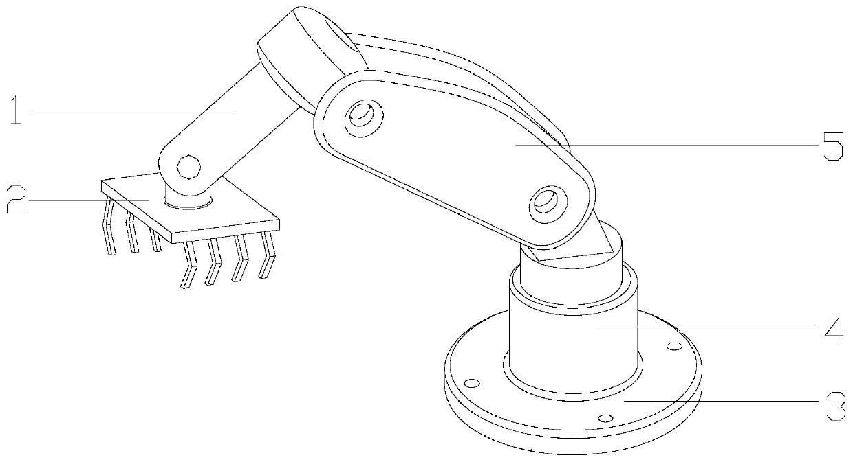
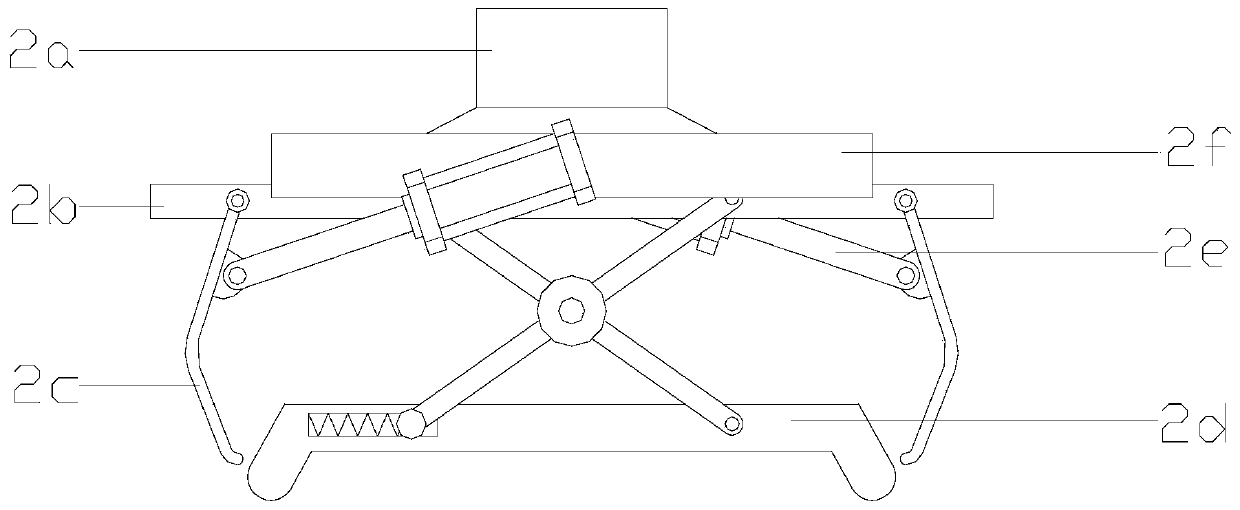
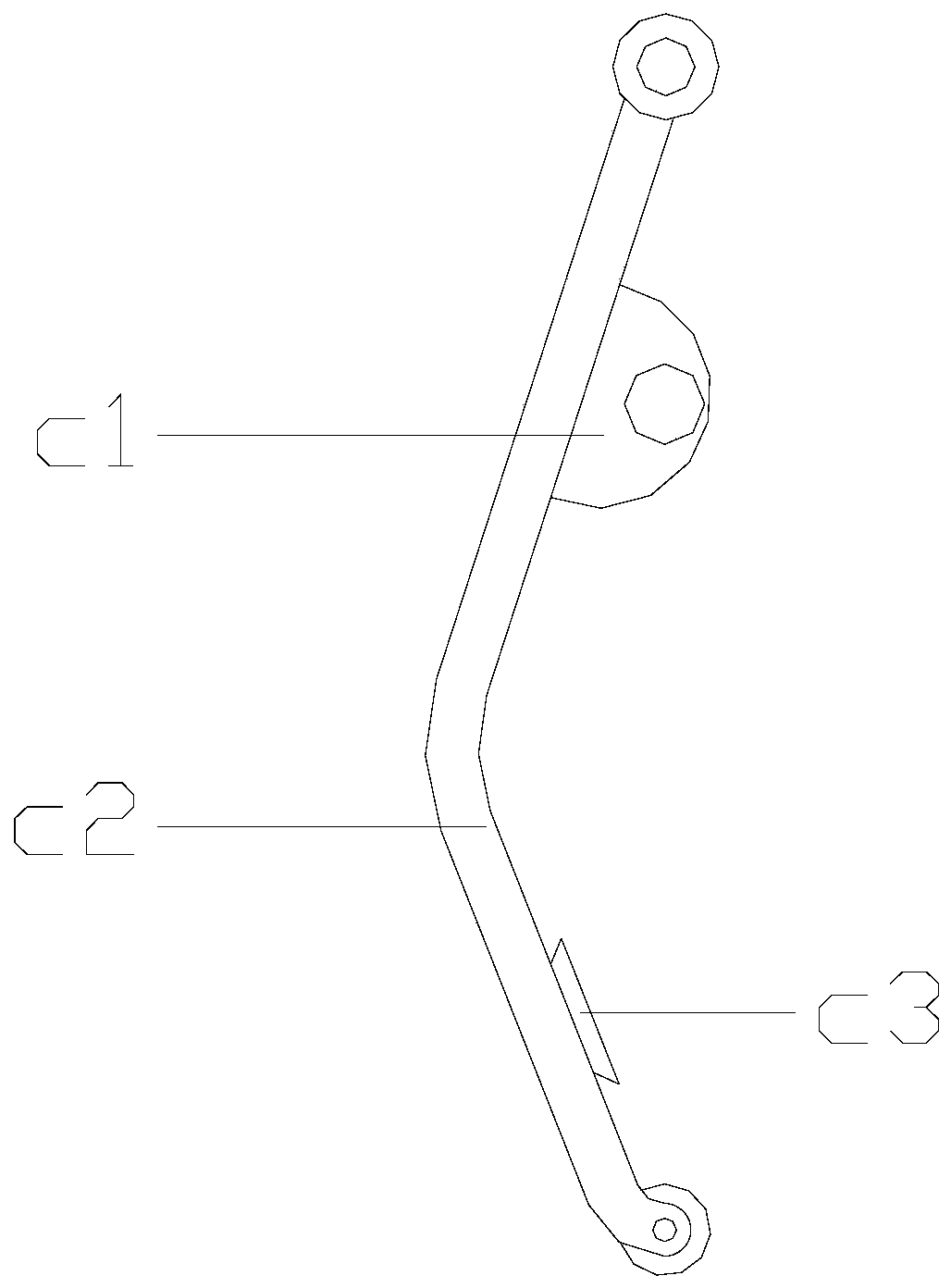
[0026] See Figure 1-Figure 2 , The present invention provides an automated palletizing device for logistics. Its structure includes a manipulator connecting arm 1, a material palletizing device 2, a fixed base 3, an automatic rotating base 4, and a driving spindle 5. The fixed base 3 has a cylindrical structure and The bottom surface and the workshop floor are fixed together by bolts, the bottom of the automatic rotating base 4 and the upper surface of the fixed base 3 are welded together, the bottom of the driving spindle 5 and the top end of the automatic rotating base 4 are fixed together by bolts, and the manipulator is connected The right end of the arm 1 is buckled with the top of the driving spindle 5. The material palletizing device 2 is located below the manipulator connecting arm 1 and parallel to the ground. The material palletizing device 2 is composed of a rotating connecting column 2a, a hand gripping fixed plate 2b, The feed fixed grip 2c, the material shaking an...


PUM


Abstract

The invention discloses an automatic stacking device for logistics. The automatic stacking device structurally comprises a manipulator connection arm, a material stacking device, a fixed base, an automatic rotating seat and a driving main shaft, wherein the automatic stacking device is combined with a material shaking and leveling mechanism through a feed fixing claw; in the process that the feedis clamped up by the stacking machine, the upper surfaces of feed bags are automatically leveled by the material shaking and leveling mechanism to avoid the condition that the uneven packaging bags are accumulated to cause feed inclination and collapse as the feeds in the bags are unevenly distributed, thereby enhancing the feed stacking stability and improving the working efficiency; and meanwhile, the condition that excursion occurs when the stacking machine drives the feed bags to rotate can be prevented to ensure that the falling positions of the feeding bags are consistent with the presetpositions, thereby enhancing the feed stacking stability and balance.

Description

Technical field [0001] The invention relates to an automated logistics system, in particular, an automated palletizing device for logistics. Background technique [0002] With the development of modern industry, human beings are gradually replacing labor with mechanical tools. The palletizing line is widely used in the transportation and palletizing of bagged materials such as flour, feed, cement, etc. The main operation is to use a palletizing robot to grab and load. Packing bags with materials are placed at fixed points, but the current technical considerations are not perfect. It has the following shortcomings: 1. The palletizer directly transports the bagged materials such as feed on the conveyor belt to the top of the shelf for stacking, but the bagged materials are In the production process, it comes out of the filling machine first, and after the sealing and bag inverting machine, the small granular materials in the bag are prone to stacking, resulting in uneven distributi...

Claims


Application Information

Patent Timeline
Patent Type & Authority Applications(China)
IPC IPC(8): B65G61/00
CPCB65G61/00
Inventor 唐永辉
Owner 姚伟波
Why Eureka
Try Eureka