Self-adaptive switching Ethernet cross redundancy backup system and self-adaptive switching Ethernet cross redundancy backup method

A technology of adaptive switching and redundancy backup, applied in the network field, can solve the problems of low link detection and switching effectiveness and flexibility, long switching time of application layer switching, single switching criterion, etc., so as to improve topology reliability. , easy to transplant and realize, the effect of strong flexibility

Active Publication Date: 2019-10-25
SHANGHAI SPACEFLIGHT INST OF TT&C & TELECOMM
View PDF6 Cites 13 Cited by
  • Summary
  • Abstract
  • Description
  • Claims
  • Application Information

AI Technical Summary

Problems solved by technology

The switching time of the application layer switching is long, and the real-time performance is low, and the switching process will inevitably cause a large amount of data loss; while the physical layer switching improves the real-time switching, but simply switches by judging the on-off status of the physical link, resulting in a single switching criterion , resulting in less effectiveness and flexibility in link detection and switching
[0004] Therefore, in view of the special requirements of high-reliability aerospace applications, there is still a lack of high-reliability system interconnection, high real-time performance, flexible and effective Ethernet backup circuits and switching control methods.

Method used


Image

  • Self-adaptive switching Ethernet cross redundancy backup system and self-adaptive switching Ethernet cross redundancy backup method
  • Self-adaptive switching Ethernet cross redundancy backup system and self-adaptive switching Ethernet cross redundancy backup method
  • Self-adaptive switching Ethernet cross redundancy backup system and self-adaptive switching Ethernet cross redundancy backup method

Examples


Embodiment Construction

[0039] The present invention will be described in detail below in conjunction with specific embodiments. The following examples will help those skilled in the art to further understand the present invention, but do not limit the present invention in any form. It should be noted that those skilled in the art can make several changes and improvements without departing from the concept of the present invention. These all belong to the protection scope of the present invention.

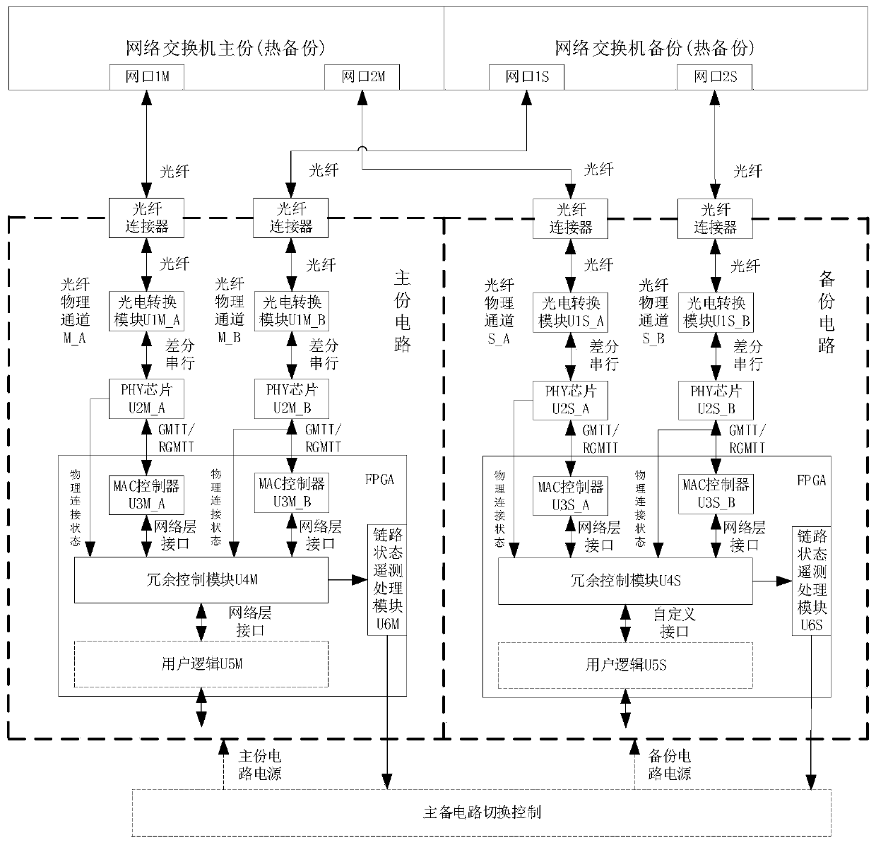
[0040]figure 1 The functional block diagram of the Ethernet cross redundancy backup system of adaptive switching provided by the present invention; figure 1 As shown, it can include primary and secondary circuits and backup circuits, wherein the primary and secondary circuits include fiber optic physical channels M_A and fiber optic physical channels M_B; backup circuits include fiber optic physical channels S_A and fiber optic physical channels S_B; fiber optic physical channels M_A, fiber optic physica...


PUM


Abstract

The invention provides a self-adaptive switching Ethernet cross redundancy backup system and method. The self-adaptive switching Ethernet cross redundancy backup system comprises a main circuit and abackup circuit which are provided with independent supply power, the main circuit and the backup circuit respectively comprise a redundancy control module. The main circuit further comprises an optical fiber physical channel M_A and an optical fiber physical channel M_B; the backup circuit further comprises an optical fiber physical channel S_A and an optical fiber physical channel S_B; the optical fiber physical channel M_A and the optical fiber physical channel S_A are both connected with the network switch main part, and the optical fiber physical channel M_B and the optical fiber physicalchannel S_B are both in backup connection with the network switch; and the redundancy control module is used for realizing self-adaptive switching of each optical fiber physical channel. The reliability of an interface circuit and topology is improved, and the method is suitable for high-reliability application fields such as space navigation; according to the invention, self-adaptive switching can be carried out when the link goes wrong, the real-time performance, the flexibility and the effectiveness of switching are improved, and the loss of a large amount of data caused by link interruption in the switching process is avoided.

Description

technical field [0001] The invention relates to the field of network technology, in particular to an adaptive switching Ethernet crossover redundancy backup system and method. Background technique [0002] As a mature commercial bus technology, Ethernet has many advantages such as flexible topology, high throughput, and support for optical fiber transmission. In aerospace applications, the primary problem facing Ethernet technology is how to improve the reliability of the Ethernet interface. In high-reliability application fields such as aerospace, in order to improve the reliability of the system interface, the method of cross-redundancy backup on the hardware is usually adopted. Traditional LVDS, RS422 and other interfaces mostly use the physical layer backup method, directly connect the main and backup interface signals through the internal connector and interface chip, and switch between the main and backup through commands. This method takes up a lot of space on the pr...

Claims


Application Information

Patent Timeline
Patent Type & Authority Applications(China)
IPC IPC(8): H04L12/24H04L12/26H04L12/703H04L12/707H04L45/24H04L45/28
CPCH04L41/0663H04L41/0836H04L43/0811H04L43/16H04L45/22H04L45/28
Inventor 朱浩文叶恒罗鹏黎泽清胡浩杨凌云方彩婷朱新忠
Owner SHANGHAI SPACEFLIGHT INST OF TT&C & TELECOMM
Why Eureka
Try Eureka