
Ball grid array antenna monitoring device

A technology for array antennas and monitoring devices, applied in antennas, antenna arrays, and structural forms of radiation elements, can solve the problems of low monitoring accuracy and failure to include antenna unit amplitude and phase characteristics, and achieve small radiation performance, small size effect

Active Publication Date: 2019-10-25
THE 724TH RES INST OF CHINA SHIPBUILDING IND
View PDF6 Cites 2 Cited by
  • Summary
  • Abstract
  • Description
  • Claims
  • Application Information

AI Technical Summary

Problems solved by technology

The disadvantage of this method is that the monitoring device only monitors the feeder part of the entire channel of the antenna, and fails to include the amplitude and phase characteristics of the antenna unit
The external monitoring device generally adopts the form of an external antenna unit, which usually needs to be erected in front of the antenna array with a pole, which will block the antenna array, and the monitoring accuracy is not high

Method used


Image

  • Ball grid array antenna monitoring device
  • Ball grid array antenna monitoring device
  • Ball grid array antenna monitoring device

Examples


Embodiment Construction

[0014] The specific embodiments of the present invention will be described in detail below with reference to the accompanying drawings.

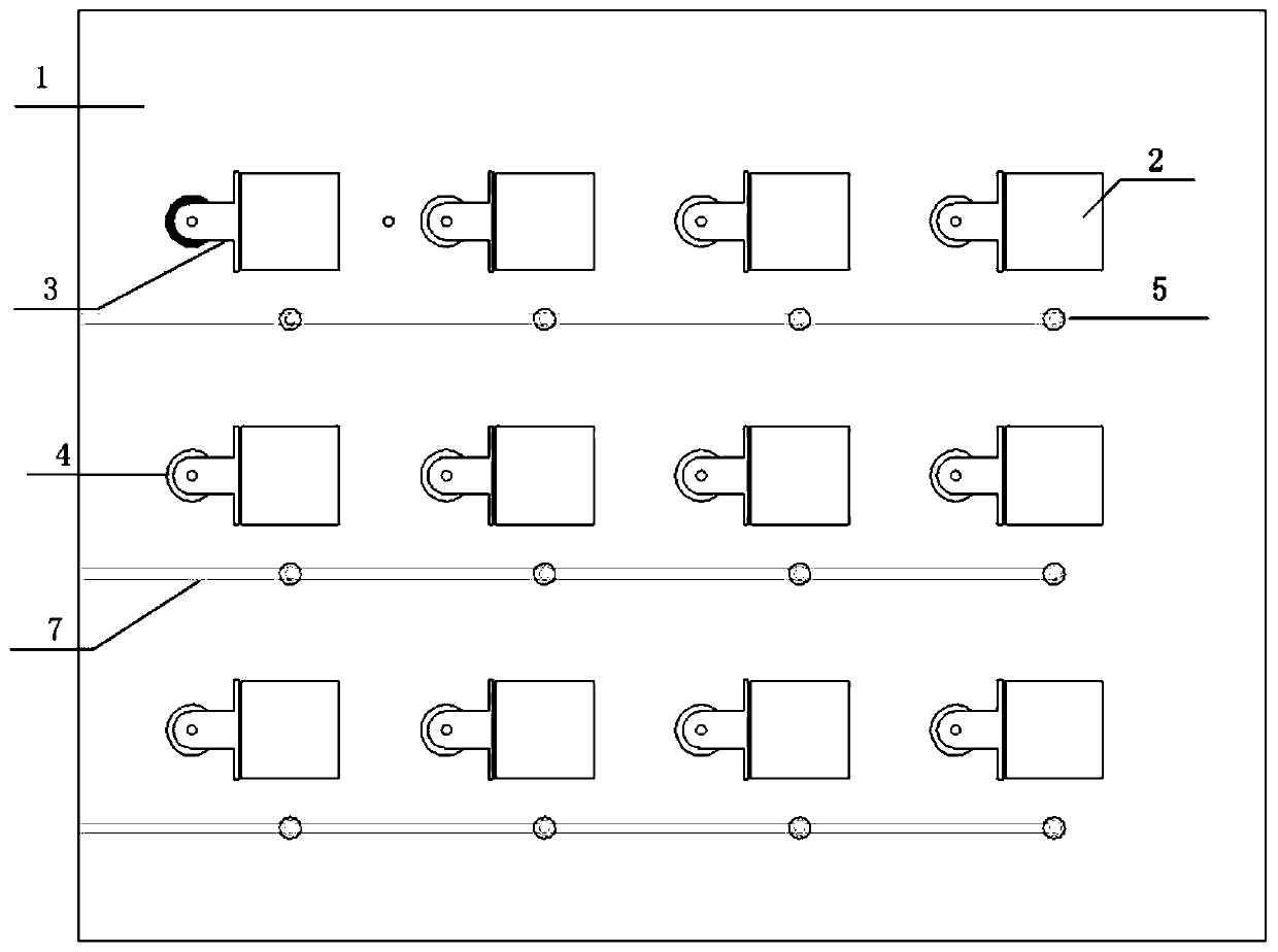
[0015] reference Figure 1 to Figure 3 In this embodiment, the ball grid array antenna monitoring device includes two parts: an antenna array and a monitoring network. It consists of a first dielectric plate 1, a second dielectric plate 8, and a third dielectric plate 9. The antenna array is a microstrip The patch antenna structure, located on the upper surface of the dielectric board 1, is composed of a microstrip patch antenna unit 2 and a microstrip feed network 3, and a metal ground 10 of the microstrip antenna on the second dielectric board 8, and is fixed to the first The radio frequency coaxial connector 4 on the tri-dielectric board 9 is connected to feed the microstrip feed network 3, in which the number of the microstrip patch antenna unit 2 is at least 4; the monitoring network consists of the ball grid array 5, metal The belt-shape...


PUM


Abstract

The invention relates to a ball grid array antenna monitoring device, which comprises an antenna array and a monitoring network and is composed of a first dielectric slab, a second dielectric slab anda third dielectric slab. The ball grid array antenna monitoring device is characterized in that the antenna array is located on the upper surface of the first dielectric slab and formed by connectinga microstrip patch antenna unit, a microstrip feed network and a metal ground, and the monitoring network is formed by connecting a ball grid array, a metalized through hole, a strip transmission line and the like. The device effectively solves a problem that the existing antenna monitoring network cannot cover part of the amplitude and phase from a feeder outlet to an antenna unit, realizes high-precision monitoring of a digital phased array radar antenna array and can be widely applied to the monitoring of the digital phased array radar antenna.

Description

Technical field [0001] The invention relates to a radar antenna monitoring device, in particular to a monitoring device for a digital phased array radar antenna. Background technique [0002] In modern radar systems, especially in digital phased array radar systems, the amplitude and phase consistency error of the channel directly affects the formation of digital beams and the accuracy of target angle measurement, and the amplitude and phase consistency errors of each channel need to be monitored and corrected. . Therefore, in the digital phased array radar system, the antenna monitoring device plays an important role. [0003] The antenna monitoring device can be divided into two forms: internal monitoring and external monitoring. At present, the antenna internal monitoring generally adopts the form of coupling line, and the energy coupling point between the monitoring device and the antenna array is located at the outlet of the antenna unit feeder to obtain amplitude and phase ...

Claims


Application Information

Patent Timeline
Patent Type & Authority Applications(China)
IPC IPC(8): H01Q23/00H01Q13/08H01Q1/38H01Q21/00
CPCH01Q1/38H01Q13/08H01Q21/00H01Q23/00
Inventor 高国明陈文俊施扬逸
Owner THE 724TH RES INST OF CHINA SHIPBUILDING IND
Learn More